background image

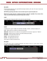
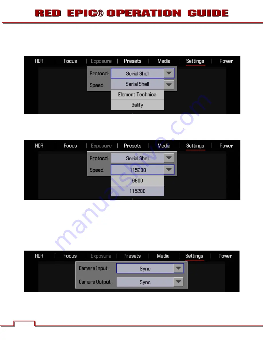
PROTOCOL 

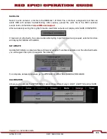
Available options are SERIAL SHELL, ELEMENT TECHNICA and 3ALITY. Default is SERIAL SHELL. 

SPEED 

Available options are 9600 baud and 115200 baud. Default is 9600 baud. 

REMOTE 

This function is not enabled at this time. 

GPIO 

GPIO selects the GPIO preferences sub-menu. 

Version 1.4.0 SVN 29352 BETA 

98

98 

©2011 RED.COM INC. 

APRIL 19, 2011 

Содержание Mysterium-X

Страница 1: ......

Страница 2: ...EFORE YOU START 7 Important Safety Instructions 7 THEORY OF OPERATION 10 MYSTERIUM X Sensor 10 Image Processing 10 HDRx 11 Magic Motion 12 Audio Recording 12 Microphone Level Analog Rear 23 Power Down 34 Graphical User Interface and Navigation 35 RED LCD Touchscreen LCD BOMB EVF External Monitors 35 Side Handle 38 F F Stop 53 1 SEC EXPOSURE 53 Basic Settings 53 Advanced Settings 53 White Balance 5...

Страница 3: ...Settings 141 Changing Camera Settings 141 Exiting Menus to Main Screen 141 APPENDIX F 3D SETUP OPERATION 142 APPENDIX G EXPOSURE USING FALSE COLOR AND ISO 143 Underexposure 2 stops 143 Overexposure 2 stops 145 Appropriate Exposure 148 Adjusting the ISO Rating 151 APPENDIX H POST PRODUCTION 153 Software Tools 154 REDCINE X 154 APPENDIX I TROUBLESHOOTING 155 No Media Attached 155 Camera Firmware Upg...

Страница 4: ... QuickTime are registered trademarks of Apple Inc Intel is the registered trademark of Intel Corporation Windows Microsoft Windows and Windows Vista are the registered trademarks of Microsoft Corporation AVID is a registered trademark of Avid Technology Inc NUKE is a trademark of The Foundry Visionmongers Ltd DISCLAIMER RED has made every effort to provide clear and accurate information in this Op...

Страница 5: ... one or more of the following measures 1 Reorient or relocate the receiving antenna 2 Increase the separation between the equipment and receiver 3 Connect the equipment into an outlet on a circuit different from that to which the receiver is connected 4 Consult the dealer or an experienced radio TV technician for help In order to maintain compliance with FCC regulations shielded cables must be use...

Страница 6: ...N COMPLIANCE STATEMENTS RED declares that the equipment described in this document is in conformance with the requirements of the European Council EMC Directive 2004 108 EC Low Voltage Directive 2006 95 EC RoHS Directive 2002 95 EC and WEEE Directive 2002 96 EC This declaration is based upon compliance of the product to the following standards x EN 55022 Information Technology Equipment Radio Dist...

Страница 7: ...t new product Disposing of this product correctly will help save valuable resources and prevent any potential negative effects on human health and the environment which could otherwise arise from inappropriate waste handling Please contact your local authority for further details of your nearest designated collection point Penalties may be applicable for incorrect disposal of this waste in accorda...

Страница 8: ...r camera lens or other accessory as doing so may expose you to electric shock and serious injury There are no user serviceable parts inside Alteration or repairs made to the camera lens or other accessory except by a RED authorized service facility will void the Limited Warranty Users are not permitted to make design changes or otherwise modify the operation of the camera lenses or other accessori...

Страница 9: ...overheating of the camera degraded operation and in extreme situations damage to the camera N DO NOT operate or store near any heat sources such as radiators heat registers stoves or any other apparatus that produce heat Store in a protected level and ventilated place Avoid exposure to temperature extremes damp severe vibration strong magnetic fields direct sunlight or local heat sources during st...

Страница 10: ...ure conditions may permanently reduce the life of the battery Available battery capacity may also be temporarily lessened after storage in low temperature conditions WARNING Do not expose the battery to excessive heat WARNING Danger of explosion if an incorrect battery is charged with the RED Charger or is used to power the camera and accessories Replace only with the same or equivalent type batte...

Страница 11: ...able frame rate imaging over 1 to 240 fps at up to 2K resolution 1 to 160 fps at up to 3K resolution and 1 to 120 fps at up to 4K or 5K resolution Native color balance for the MYSTERIUM X sensor is 5 000 degrees Kelvin but it may be electronically compensated for any color temperature in the range 1 700 to 10 000 degrees Kelvin White balance preset values include Tungsten 3200K and Daylight 5600K ...

Страница 12: ...ate exposures This is important to note because if they were two standard alternating exposures there would be a time gap between the two tracks that would show up as an undesirable motion artifact Both tracks A X are stored in a single R3D file Since there are two exposures when in HDRx mode the camera is recording double the amount of frames For example if you are shooting 24fps the camera is re...

Страница 13: ...r channels of microphone level or line level audio inputs when equipped with a PRO I O Module that are synchronized with video and timecode to REDMAG 1 8 SSD media Input signals are routed via a high quality pre amplifier and soft clip limiter in order to achieve the desired audio reference recording level and to maximize dynamic range To assist with audio reference level setup the camera provides...

Страница 14: ...ng camera GUI timecode clip name and framing guides the specific overlay graphics for each type of output is user configurable The default VIEWFINDER output is the EVF LCD connector located on the front face of the Side SSD Module If neither of these is connected VIEWFINDER output will be automatically transferred to the HDMI output or it may be selected by the operator to appear on the HD SDI out...

Страница 15: ...ects such as 2 40 1 and 16 9 Focus aided by high display resolution 1 1 Focus Check function and False Color overlay Exposure aided by dual Zebras False Color overlay RAW Traffic Lights and RGB histogram System information including current frame rate ISO rating shutter speed color temperature record resolution record quality clip name timecode value and the remaining battery and media capacity Fo...

Страница 16: ...eed White Balance ISO and programmable User Keys An integrated color LCD displays camera parameters media and battery capacity and REDmote menus Figure 3 REDmote LCD display REDmote includes a rechargeable Li Ion battery which automatically re charges when attached to the camera or rearmost module It may also be re charged by connecting to a USB 2 based power source such as a laptop P C or cell ph...

Страница 17: ... extension RDM This folder contains all clips recorded on that digital magazine therefore copying these clips from the digital magazine to backup media may be performed by a single drag and drop operation For additional information about digital magazines refer to APPENDIX B MANAGING DIGITAL MEDIA METADATA RED EPIC cameras record extensive Metadata which is data that describes the precise characte...

Страница 18: ...sitioned as the right R camera in the 3 D configuration Assuming the master camera is slated as camera S Clips recorded using the Master and Slave camera configuration to shoot 3 D footage would look like S001_L001_1206 RDC and S001_R001_1206 RDC NOTE L left and R right file name designations may be adjusted if desired in the MEDIA menu SMPTE TIMECODE Edge Code is a SMPTE timecode track that alway...

Страница 19: ...PTION The camera draws approximately 60 watts when recording in 5K resolution 24fps MOVIE mode The camera is cooled by convection from the camera body assisted by a fan contained in a sealed air duct Under typical operating conditions a RED VOLT XL 90Wh battery will run the camera and accessories for about 90 minutes A RED VOLT 30Wh battery will run the camera and accessories for about 30 minutes ...

Страница 20: ...Record Button C Record Status LED Figure 4 Power Record Button Status LEDs A B A C x Power Status LED Indicates Status of Power Power Available Not Available Power O K x Power Record Button Powers camera Up Down and initiates Record Stop Start x Media Status LED Indicates status of Media Media Available Not Available Media Recording Version 1 4 0 SVN 29352 BETA 19 APRIL 19 2011 2011 RED COM INC ...

Страница 21: ...nction Default 1 1 Magnify x User Key 2 Initiates user defined camera function Default False Color Exposure x User Key 1 User Key 2 Press both keys to Eject unmount REDMAG 1 8 SSD Media x Focus Record Button Touch for Auto Focus fully depress to Start or Stop Record x Media Indicator When media is inserted and ready to record the LED illuminates Green When no media is present the LED is off Versio...

Страница 22: ...Releases Side Handle battery door to permit battery exchange Focus Record Button Touch for Auto Focus fully depress to Start or Stop Record Adjustment Ring Selects and adjusts camera parameter values LCD Menus Keys Specific functions are defined by LCD screen LCD Display Displays key camera parameter values x LCD Backlight Button Enables LCD backlight Version 1 4 0 SVN 29352 BETA 21 APRIL 19 2011 ...

Страница 23: ...de Handle Controls Front x Stills Movie Slider Selects between STILLS and MOVIE modes of operation NOTE This switch is not active at this time Default camera operation is MOVIE Version 1 4 0 SVN 29352 BETA 22 22 2011 RED COM INC APRIL 19 2011 ...

Страница 24: ... Group F Thumbwheel Lock A B C D E F Figure 8 RED Side Handle Controls Rear x x Rocker Switch Increases or decreases selected value based on parameter selected in USER KEYs Menu Button Press to access camera setup menus Version 1 4 0 SVN 29352 BETA 23 APRIL 19 2011 2011 RED COM INC ...

Страница 25: ...elected parameter value adjustment x User Keys User Function Keys A D F The specific function of these keys may be programmed by the user Default settings for User Function Keys A D are as follow User Key A Enables Auto Focus Indicator User Key B Enables White Balance calculation User Key C Enables 1 1 Focus Check User Key D Enables false color Exposure Check x System Keys Function are defined by ...

Страница 26: ...side handle into the area where the lip from the side plate was installed 4 Rotate side handle down flush along side of camera brain 5 Rotate thumbscrew upwards until tight Ensure side handle is secure to camera brain Remove screw and rotate side plate upwards to remove Insert lip into top of camera brain Press side handle flush against camera brain Rotate thumbscrew upwards until tight Version 1 ...

Страница 27: ...dy Disengage lip from top of camera brain Rotate side handle upwards to remove Rotate thumbscrew downwards until loose 2 Rotate upwards to disengage lip at top of side handle from camera brain 3 Remove side handle from camera Version 1 4 0 SVN 29352 BETA 26 26 2011 RED COM INC APRIL 19 2011 ...

Страница 28: ...I O N K L M x Stills Motion Slider Allows selection of STILLS or MOVIE operational modes x Rocker Switch Provides continuous adjustment of parameter specified in USER KEYS menu x User Keys Press to initiate camera functions as defined in USER KEY menu Default settings for User Function Keys A D are as follow User Key A Enables Auto Focus Indicator User Key B Enables White Balance calculation User ...

Страница 29: ...rection Keys C Enter Button Scroll Wheel Selects and adjusts selected camera parameter value Direction Keys Navigates camera menus and may select parameter for adjustment Enter Button Confirms selected parameter value adjustment x Focus Record Button Touch for Auto Focus fully depress to Start or Stop Record x Soft Menus Keys 4 8 Functions defined by LCD screen Not active at this time x Power Lock...

Страница 30: ...ptimal subject focus for your eye Available diopter range is 2 0 to 5 0 x EVF User Key 1 Initiates user defined camera function Default 1 1 Magnify x EVF User Key 2 Initiates user defined camera function Default False Color Exposure A B C Version 1 4 0 SVN 29352 BETA 29 APRIL 19 2011 2011 RED COM INC ...

Страница 31: ...st B Power Key C LCD User Key x Backlight Adjust Adjusts LCD backlight intensity x Power Key Not Used x LCD User Key Press to execute user defined function Default False Color Exposure Version 1 4 0 SVN 29352 BETA 30 30 2011 RED COM INC APRIL 19 2011 ...

Страница 32: ...chscreen LCD also allows navigation of camera menus and selection and adjustment of camera parameters by directly touching icons on the screen Gestures supported include x Tap Tap on an icon to bring up a quick adjustment display x Hold Touch and hold on an icon to bring up an advanced interface display x Slide Touch and slide on an icon to increment a value x Pinch Touch with two fingers then ope...

Страница 33: ... MOVIE mode Figure 15 Side Handle Battery Compartment EXTERNAL DC POWER EPIC accepts input voltages between 11 5V 17V D C and can draw a maximum current of 12 Amps x An appropriate 150W supply with DC output rated at 15V 10A is available from RED Digital Cinema x RED BRICK 140Wh batteries may be used with the camera via an adaptor cable p n 140 0135 x 4 pin XLR DC power sources may also be used wi...

Страница 34: ... and within 5 seconds illuminate Orange to confirm the camera is powering up then it will illuminate Green confirming the camera is powered up and ready to use If a formatted REDMAG 1 8 SSD is attached to the Brain once powered up the Media Status LED will illuminate Green If this LED is not illuminated verify a formatted REDMAG 1 8 SSD is inserted into the Side SSD Module and or format the SSD if...

Страница 35: ...After Power Down the Power Status LED will illuminate Red if an appropriate power source is available NOTE The camera may also be powered down using REDmote or Side Handle Menu controls or via Touch Screen LCD icons Refer to SECONDARY MENUS POWER Version 1 4 0 SVN 29352 BETA 34 34 2011 RED COM INC APRIL 19 2011 ...

Страница 36: ...E MEDIA TC DROP LAN STATUS HISTOGRAM RESOLUTION PROJECT FRAME RATE QUALITY RAW NOISE LEVEL BAR RAW CLIP METER RAW CLIP LEVEL BAR FAN SPEED GENLOCK MAGNIFY JAMSYNC GPS STATUS POWER AUDIO METER Figure 17 GUI Display Elements The display elements include x Frame Rate Current frame capture rate x Quality REDCODE setting x ISO Rating Camera sensitivity x Cursors Reference cursors Safe Action Safe Title...

Страница 37: ...pply voltage x Audio Meter Audio input selection and levels x Timecode Current timecode value x Menu ICON In the upper right corner on the touchscreen LCD Opens the Secondary Menus The GUI is broken down into the following three main sections the Upper Status Row the Live Action Area and the Lower Status Row On VIEWFINDER output s all three sections are visible on PREVIEW outputs only the Live Act...

Страница 38: ...he ENTER key has been pressed This reveals the Parameter Adjust Widow Adjust the value using the Scroll Wheel and then press ENTER to confirm the value change then close the sub menu LIVE ACTION AREA Contains the recorded image area plus Surround View look around area plus overlays for Frame Guide Safe Action Safe Title and the current Clip Name and Timecode values Each overlay may be color coded ...

Страница 39: ...ining battery capacity and the display text is color coded as follows x Green 99 11 x Yellow 10 6 x Red 5 0 NOTE If using a REDBRICK battery to power the camera power status displays DC and voltage as if the camera is hooked up to DC power SIDE HANDLE The display elements include x Power Camera power status DC Shown x ISO Rating Camera sensitivity x Frame Rate Image capture rate x Shutter Speed Ex...

Страница 40: ...to Exposure Not active at this time x Timecode Current timecode value x Battery Camera battery life status x Media Remaining media capacity x Clip Meter RGB sensor RAW clipping status NAVIGATING MENUS The primary method to navigate Menus is via the Scroll Wheel Rotate clockwise to move right counter clockwise to move left However the Left and Right direction Navigation Keys may also be used for th...

Страница 41: ...y simply touching that section of the screen x Touching Clip Settings at the lower Left corner of the LCD will display the System Status screen Refer to SECONDARY MENUS SETTINGS MAINTENANCE SYSTEM STATUS for complete information x Touching the RGB Histogram will bring up the False Color overlay menu Refer to SECONDARY MENUS SETTINGS DISPLAY FALSE COLOR for complete information x Touching System St...

Страница 42: ...located between the audio channels and media remaining indicator to reveal the same menu illustrated above 2 Select SHUTDOWN 3 The camera will immediately power down LOCK UNLOCK TOUCHSCREEN OPRERATION LOCK To lock out the touchscreen operation touch and hold the MENU icon until the LOCK icon displays indicating the touchscreen has been locked out When locked the main menu will be displayed Version...

Страница 43: ...k out the touchscreen and allow normal operation touch and hold the LOCK icon until the MENU icon displays indicating the touchscreen has been unlocked Version 1 4 0 SVN 29352 BETA 42 42 2011 RED COM INC APRIL 19 2011 ...

Страница 44: ... insert a REDVOLT battery Install 1 Press the battery door release button A 2 Open battery door B 3 Press upwards on retainer C 4 Insert a REDVOLT battery until it is fully seated and retainer C clicks into place A B C 5 Close battery door Remove 1 Press the battery door release button A 2 Open battery door B Version 1 4 0 SVN 29352 BETA 43 APRIL 19 2011 2011 RED COM INC ...

Страница 45: ...e output trips for any reason remove any external loads from the camera such as lights motors etc turn off the Adapter and repeat the above procedure 2 POWER UP Locate the camera s Power ON OFF button on the right face of the Brain If the Power Status LED is illuminated Red depress and then release the Power Record button If not illuminated check your battery charge status or external power source...

Страница 46: ...formatting PERFORMING A BLACK SHADING CALIBRATION Reformat the SSD media Frame focus and record CONNECTING AND FORMATTING MEDIA Identify a REDMAG 1 8 64GB 128GB or 256GB SSD that has not previously been recorded to or is not a camera master and may therefore be erased and re used Aligned the RED logo of the SSD to the outside and then push the SSD firmly but without excessive force into the slot i...

Страница 47: ...s this defines the frame count to be used for time code and as the clip playback and editing frame rate It is also the primary frame rate for acquisition but variable speed over crank and under crank recordings can be made above and below this base frame rate using the VARISPEED menu RECORD RESOLUTION To adjust Record Resolution navigate the Cursor to the RESOLUTION icon in the Upper Status Row an...

Страница 48: ... each clip recorded on the SSD based on the Camera s I D set in the MEDIA menu REDCODE RAW data recordings store the Color Temperature and Exposure ISO and any RGB color processing values you use in the monitor path as metadata This metadata is used in REDCINE X or other post production software as initial white balance exposure and color correction points however you are free to change these valu...

Страница 49: ...nabled SMPTE RP188 timecode VITC 2 HANC metadata record flag will be enabled on HD SDI outputs If enabled in the USER KEYS menu the GPO trigger output in the CNTL connector will pulse 5 PLAYBACK Playback of recorded clips is not currently enabled in camera firmware and must be performed off the camera Off load the Clips from your REDMAG 1 8 SSD to a personal computer using a RED STATION REDMAG 1 8...

Страница 50: ...ss ENTER to set TOUCHSCREEN x Touch the desired parameter for adjustment x Slide your finger across the screen to scroll through the available parameter values x When desired the parameter value has been selected touch anywhere in the screen area to set x To close an alpha numeric keypad when entering information directly tap anywhere on the screen outside the keypad ADVANCED SETTING MENUS At this...

Страница 51: ... to advanced setting adjustments 2 Press the field a keypad type menu may appear to allow adjustments 3 Press the desired parameter settings to adjust 4 When desired selection is made press anywhere in the screen area to set and exit the advanced settings submenu Version 1 4 0 SVN 29352 BETA 50 50 2011 RED COM INC APRIL 19 2011 ...

Страница 52: ...a frame rate other than the current TIME BASE has been selected the FPS text will turn Yellow and VARISPEED will be shown where the Audio Meter is normally displayed at the lower right of the display If you press record with a frame rate set too high for the selected record quality you will be prompted to allow the camera to change the REDCODE setting to the maximum quality that enables that frame...

Страница 53: ...lue Touch the value bounded by the and labels to bring up press outside the keypad to confirm the value ISO SENSITIVITY Adjusts the camera s ISO rating The sensitivity value is adjustable in 1 3rd stop increments When the ISO rating is adjusted the camera logs the change as metadata and the monitor path reacts accordingly Higher ISO values lead to brighter images in the monitor path and vice versa...

Страница 54: ...ng within the frame Increasing Shutter Speed increases allows less light to fall on the sensor decreasing exposure and motion blur on objects moving within the frame Range is 1 sec 1 8000th sec Slowest available speed is 1 frame rate so for 24 fps it is 1 24th sec Default is 1 48th Sec ADVANCED SETTINGS When selected the advanced settings menu allows fine control over the Exposure value and permit...

Страница 55: ...west available speed is 1 frame rate so for 24 fps it is 1 24th Sec Default is 1 48th Sec TIME Provides the ability to enter the Exposure value as a Shutter Integration Time xx milliseconds Range is 0 125 to 1 000 mS milliseconds Default is 20 833 MS Version 1 4 0 SVN 29352 BETA 54 54 2011 RED COM INC APRIL 19 2011 ...

Страница 56: ...es To Convert Shutter Speed to Angle Equivalent Equivalent Degrees Shutter Speed x Frame Rate x 360 E g 1 48 x 24 x 360 8640 48 180 Shutter Degrees Shutter Degrees 1 32 270 1 120 72 1 48 180 1 192 45 1 50 172 8 1 348 22 5 1 60 144 1 696 11 1 96 90 1 1000 8 6 Equivalent Shutter 1 Frame Rate x 360 Angle E g 1 24 x 360 180 1 8640 180 1 48 Degrees Shutter Degrees Shutter 270 1 32 72 1 120 180 1 48 45 ...

Страница 57: ...justment of the White Balance Available options are PRESET COLOR TEMP TINT and CALCULATE WHITE BALANCE Press APPLY for settings to take effect PRESET Available preset options are SHADE Preset to 9 000K DAYLIGHT Preset to 5 600K FLOURESCENT Preset to 4 500K INCANDECENT Preset to 2 800K CLOUDY Preset to 7 500K FLASH Preset to 5 500K TUNGSTEN Preset to 3 200K Version 1 4 0 SVN 29352 BETA 56 56 2011 R...

Страница 58: ...he TINT parameter can adjust the RGB color balance with a compensating Magenta Green color component Default is 0 When selected a secondary keypad will appear allowing you to enter the desired Tint value directly NOTE Selecting Calc White Balance calculates a new Tint value This is maintained if the Color Temp is adjusted via the Color Temp parameter If you select ANY presets Tint will be reset to...

Страница 59: ...ct the Calc White Balance function and then press the Calc White Balance function box Calc White Balance is also assigned to a User Key on the REDmote and Side Handle as a factory default setting RESOLUTION Allows adjustment of resolution Default is 5K 2 1 The following Resolution options are available x 5K 2 1 x 5K FF x 5K 2 4 1 REDCODE Allows adjustment of REDCODE settings Range is 2 1 to 18 1 D...

Страница 60: ...Version 1 4 0 SVN 29352 BETA 59 APRIL 19 2011 2011 RED COM INC ...

Страница 61: ...DR ON OFF By default HDR is OFF HDR button is illuminated Blue In the Lower Status Group of the Viewfinder screen the HDR text is Gray indicating HDR is inactive To turn HDR on navigate to the HDRx button using the Nav Group and press ENTER or from the touchscreen directly touch the HDRx button Press the HDRx button which will turn Blue In the Lower Status Group of the Viewfinder screen the HDR te...

Страница 62: ...ters including MODE and ZONES MODE To adjust the MODE parameter select the Menu box and use the UP DOWN arrows to adjust Available options are OFF and FOCUS CONFIRM Default is OFF If selected FOCUS CONFIRM places a single box or a grid of boxes on the screen depending on the ZONES selection that indicate where the image is in focus Version 1 4 0 SVN 29352 BETA 61 APRIL 19 2011 2011 RED COM INC ...

Страница 63: ...the square will be Yellow or Green When objects located in the circle are out of focus the circle will be Red The manual focus square can be moved around the screen Tap on the manual focus square and drag to the location you wish to relocate the manual focus square to The manual focus square can be resized Tap two times on the square to increase size You can increase the size 3 times After that wh...

Страница 64: ...cus the circle will be Red MATRIX Provides a many targets for focus When many objects on the screen are in focus many boxes will be Yellow or Green When few objects on the screen are in focus few boxes will be Yellow or Green Red boxes indicate objects that are out of focus EXPOSURE MENU Not implemented at this time Version 1 4 0 SVN 29352 BETA 63 APRIL 19 2011 2011 RED COM INC ...

Страница 65: ...lected allows you to create your own preset and decide which information will be stored with that preset After Preset name is entered and Preset information is highlighted select CREATE to create your preset and will be taken back to the Preset Main Menu your new preset shown NOTE If more presets are available they will be accessible by using the arrow keys on either end of the Preset name field V...

Страница 66: ...ss the Menu button to close the keyboard PRESET INFORMATION Use the arrow keys and Enter button to select the information you want to be stored for your preset Available options are IMAGE SYSTEM PROJECT KEYS and or OUTPUT When creating a new preset successfully completed Preset Created Successfully will appear and the preset will be listed Version 1 4 0 SVN 29352 BETA 65 APRIL 19 2011 2011 RED COM...

Страница 67: ... 8 SSD to the camera or apply available RMD presets CAMERA PRESETS When EXPORT PRESET is selected this will export the CAMERA PRESTS from the camera to the external memory 1 8 SSD Once a preset is exported it will appear as a selection in the DISK PRESETS field NOTE If external memory is not connected the Export Preset function cannot be performed When successfully completed Preset Exported Succes...

Страница 68: ...e asked if you want to apply the imported preset If No is selected the preset will be imported and listed in the available Camera Presets If Yes is selected Preset Applied Successfully will appear when successfully completed The preset will be listed in the available Camera Presets If the preset could not be applied Preset Could Not Be Applied will appear to inform you APPLY When APPLY is selected...

Страница 69: ...te a new one or import and existing one from external media You will be asked to confirm if you want to delete the preset When successfully completed Preset Deleted Successfully will appear MEDIA MENU The Media Menu is used to format media SSD prior to use on the camera as well as to Eject unmount the media prior to removal from the camera Available options when selected are SELECT MEDIA SET MEDIA...

Страница 70: ...nt Media box when formatting Available options are REEL NO CAM ID CAM POS and SET to set the values entered REEL NO When selected a keypad will appear allowing you to enter a value between 1 and 999 CAMERA ID SLATE Identifies the camera with a letter A through Z Default is A CAMERA POS POSITION Identifies the camera position as Right Left or Center Default is Center Version 1 4 0 SVN 29352 BETA 69...

Страница 71: ... CAM POS and FORMAT to format the media with the values entered REEL NO When selected a keypad will appear allowing you to enter a value between 1 and 999 CAMERA ID SLATE Identifies the camera with a letter A through Z Default is A CAMERA POS POSITION Identifies the camera position as Right Left or Center Default is Center Version 1 4 0 SVN 29352 BETA 70 70 2011 RED COM INC APRIL 19 2011 ...

Страница 72: ...he digital magazine is ready for immediate use EJECT MEDIA When selected will Eject unmount the media highlighted in the Select Media box When ejected camera will display Media Ejected Successfully SETTINGS MENU This section describes the various secondary controls available to configure the camera Menu options are DISPLAY LOOK SENSOR PROJECT MODES AUDIO VIDEO SETUP and MAINTENANCE Version 1 4 0 S...

Страница 73: ...iew modes Default is OFF EXPOSURE EXPOSURE displays a 2 color overlay that allows you to check minimum and maximum exposure levels of the RAW sensor data and hence prevent underexposed or overexposed images When selected the icon E will be displayed in the Lower Status Group The EXPOSURE meter s color bands provide the following information PURPLE Minimum Exposure RED Maximum Exposure Between mini...

Страница 74: ...r changing the KNEE and WHITE values of the CURVE box VIDEO VIDEO displays a multi color color overlay that allows you to check the video level of the RGB monitor path calibrated to the SMPTE test signal and any outputs driven from that path such as HD SDI and HDMI When selected the icon V will be displayed n the Lower Status Group Purple represents Super Black Dark Blue represents Black Teal repr...

Страница 75: ...ay Card IRE 44 47 PINK Typical level for Caucasian Skin IRE 54 57 STRAW White IRE 96 98 YELLOW Super White IRE 101 104 ORANGE Super White IRE 105 107 RED Super White IRE 108 109 At all other values the monochrome image displayed represents the luminance value of the ISO adjusted image Version 1 4 0 SVN 29352 BETA 74 74 2011 RED COM INC APRIL 19 2011 ...

Страница 76: ...overlay that outlines the edges of objects that are in sharp focus By adjusting your lens zoom and focus you can see which objects are coming into and falling out of focus When selected the icon F will be displayed in the Lower Status Group RAW the Lower Status Group Version 1 4 0 SVN 29352 BETA 75 APRIL 19 2011 2011 RED COM INC ...

Страница 77: ... will automatically exit this mode When using a touchscreen you can also perform this function by pinching your fingers together and apart ZEBRA Zebras enable and adjust the upper and lower values for two independent Zebra indicators One zebra may be used for highlight exposure and the other for mid tone or shadows By default Zebra 1 and 2 are disabled Version 1 4 0 SVN 29352 BETA 76 76 2011 RED C...

Страница 78: ...ing between 93 and 109 default is 108 Low IRE Change the desired setting between 75 and 107 default is 99 ZEBRA 2 To enable select ZEBRA 2 check box Areas of the image exposed within these ranges will be indicated by crosshatched overlays at 45 degrees relative to vertical Zebra 2 is shown in the image below High IRE Change the desired setting between 1 and 99 default is 1 Version 1 4 0 SVN 29352 ...

Страница 79: ...izon AF Zones AE Zone Faces Center and GRID LOOK AROUND is always enabled Transparency The transparency setting for AF ZONES AE ZONE FACES CENTER GRID and LOOK AROUND may be adjusted Options are 0 25 50 75 and 100 Color The color setting for AF ZONES AE ZONE FACES CENTER GRID and LOOK AROUND may be adjusted Options are White Blue Yellow Green Red or Black Select the color that provides maximum con...

Страница 80: ...nts are Exposure Aperture Time Code and GUI Skin EXPOSURE Selects GUI display of Shutter Exposure as Time 1 xx sec or Angle Degrees APERTURE Selects GUI display of f stop as 1 4 f Stop or 1 3 f Stop TIME CODE Selects GUI display of Timecode as Time of Day TOD and Edge Version 1 4 0 SVN 29352 BETA 79 APRIL 19 2011 2011 RED COM INC ...

Страница 81: ...ackground for indoor shooting conditions Outdoor Outdoor displays the menu items in Black text over a Gray background for outdoor shooting conditions Night Night displays the menu items in Red text over a Gray background for nighttime shooting conditions Version 1 4 0 SVN 29352 BETA 80 80 2011 RED COM INC APRIL 19 2011 ...

Страница 82: ...title guides may be saved as a USER PREFERENCE thereby permitting the camera guides to be fully customized for any application Available options are Size Color and Transparency SIZE Available options are Off Full 2 39 1 1 85 1 16 9 4 3 1 9 1 or User Full is illustrated below Version 1 4 0 SVN 29352 BETA 81 APRIL 19 2011 2011 RED COM INC ...

Страница 83: ... Offsets X Y COLOR Sets the frame guideline color to White Blue Yellow Green Red or Black Select the color that provides maximum color contrast with the scene you are shooting TRANSPARANCY Sets the frame guide transparency Available options are 0 25 50 75 and 100 Version 1 4 0 SVN 29352 BETA 82 82 2011 RED COM INC APRIL 19 2011 ...

Страница 84: ...AREA GUIDES Area Guides displays Title Guides and Action Guides Version 1 4 0 SVN 29352 BETA 83 APRIL 19 2011 2011 RED COM INC ...

Страница 85: ...ions are OFF 16 9 14 9 4 3 2 4 1 1 85 1 and User Default is OFF User Title Guide and Action Guide can be set to your own preferences through User Settings Available options are Aspect Ratio and Scale Version 1 4 0 SVN 29352 BETA 84 84 2011 RED COM INC APRIL 19 2011 ...

Страница 86: ... Yellow Green Red or Black Select the color that provides maximum color contrast with the scene you are shooting TRANSPARENCY Sets Title Guide and Action Guide transparency Options are 0 25 50 75 and 100 Version 1 4 0 SVN 29352 BETA 85 APRIL 19 2011 2011 RED COM INC ...

Страница 87: ...for a dimmer display TOUCH GESTURES These options apply ONLY to the Touchscreen LCD Pinch to Magnify When selected allows you to use two fingers in a pinching motion on the screen to enable Focus Zoom To zoom out to normal view slide fingers apart Double Click Right 25 to Record When selected the right 25 of the screen can be double tapped to start and double tapped again to stop recording Version...

Страница 88: ...menu permits adjustment of SATURATION CONTRAST and BRIGHTNESS SATURATION Adjusts color saturation Range is 0 0 monochrome to 2 0 super color Default is 1 0 CONTRAST Adjusts the overall contrast of the image Range is 1 0 flat to 1 0 max contrast Default is 0 0 BRIGHTNESS Adjusts brightness without crushing highlights Available range is 10 to 10 Default is 0 0 Version 1 4 0 SVN 29352 BETA 87 APRIL 1...

Страница 89: ...ault is 1 0 GREEN Adjusts the gain of the GREEN channel only Range is 0 0 no Green to 4 0 Default is 1 0 FLUT The FLUT sub menu permits adjustment of FLUT EXPOSURE COMPENSATION and SHADOW FLUT FLUT Floating Point Lookup Table adjusts mid range tone values Range 4 0 to 4 0 Default is 0 0 EXPOSURE Adjusts exposure compensation Available exposure range is 7 0 to 7 0 Default is 0 0 Version 1 4 0 SVN 2...

Страница 90: ...CURVE sub menu permits adjustment of the monitor output Color Space and Gamma curve Available options are REDGamma2 and REDLogFilm SENSOR Defines operational modes for the SENSOR Available options are SHUTTER and SYNC SHUTTER Enables one of two shutter timing duration modes Absolute or Relative Default selection is Absolute ABSOLUTE Shutter Speed is defined exclusively by the Shutter Speed setting...

Страница 91: ...DE Available options are OFF GENLOCK SHUTTER INTERNAL PROXY and SLAVE Default is Off OFF Shutter start time is defined by internal camera timing GENLOCK Shutter start time is slaved to an external RS170A tri level sync signal a k a Genlock SHUTTER Shutter start time is slaved to an external Shutter Sync signal INTERNAL Not implemented at this time PROXY Not implemented at this time SLAVE Not imple...

Страница 92: ...TERNAL TC and INTERNAL USER PROVIDED TC USE RTC TIME USE AATON SERIAL and SET MANUALLY EXTERNAL TC When selected the camera reads the external SMPTE timecode signal and synchronizes its internal timecode counter to that value at the beginning of each recording INT USER PROVIDED TC Use RTC Time When selected the camera uses the camera s Real Time Clock as the timecode counter source Use Aaton Seria...

Страница 93: ...o define a custom value as the timecode counter seed MODES This menu is currently not operational AUDIO VIDEO Menu adjusts AUDIO INPUT AUDIO OUTPUT MONITOR CONTROL and TEST SIGNALS Version 1 4 0 SVN 29352 BETA 92 92 2011 RED COM INC APRIL 19 2011 ...

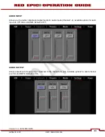
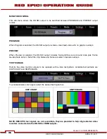
Страница 94: ...l 1 4 Available options for each input are OFF BAL and UNB Default is OFF AUDIO OUTPUT Allows adjustment of audio output levels fed to the Headphone jack Available options for each channel are VOL and MUTE Default is VOL Version 1 4 0 SVN 29352 BETA 93 APRIL 19 2011 2011 RED COM INC ...

Страница 95: ... Guides Safe Action Safe Title Clip Name and frame accurate Timecode overlays TEST SIGNALS Permits the video monitor outputs to be replaced with a video test pattern Available test patterns are CHIP CHART and SMPTE BARS To enable disable a test signal select the desired test signal box CHIP CHART SMPTE BARS NOTE RED EPIC test signals are not recordable they are provided to help align external vide...

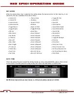
Страница 96: ...ser Keys on the camera body and accessories User keys are also referred at as Soft Keys Buttons USER KEY NOTE To reset keys to default settings go to RESTORE A reboot of the camera is necessary to restore defaults NOTE Multiple keys can be programmed to the same action Use this menu to select and program the camera USER KEYS A D USER A Default is AF MODE USER B Default is WB CALC USER C Default is...

Страница 97: ...x Record Stop x AF Refocus x Zoom In Speed 3 x Toggle SH Backlight x Menu Left x Zoom In Speed 4 x Menu Up x Menu Right x Zoom Out Speed 1 x Menu Down x Menu Toggle x Zoom Out Speed 2 x Rotary Next Value x TC Jamsync x Zoom Out Speed 3 x Rotary Previous Value x Shutter Sync x Zoom Out Speed 4 x Set Focus Mode For Still x False Color x Brain LCD Br Up x Set Focus Mode for Movie x Next Value x Brain...

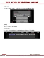
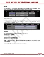
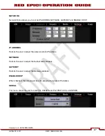
Страница 98: ... be auto assigned a dynamic IP address SERIAL This menu allows the user to select the RS232 Serial Port PROTOCOL and SPEED NETWORK Network Menu allows you to set an IP ADDRESS NETMASK GATEWAY and ENABLE DHCP IP ADDRESS Permits the user to adjust the camera s static IP address NETMASK Version 1 4 0 SVN 29352 BETA 97 APRIL 19 2011 2011 RED COM INC ...

Страница 99: ...ALITY Default is SERIAL SHELL SPEED Available options are 9600 baud and 115200 baud Default is 9600 baud REMOTE This function is not enabled at this time GPIO GPIO selects the GPIO preferences sub menu Version 1 4 0 SVN 29352 BETA 98 98 2011 RED COM INC APRIL 19 2011 ...

Страница 100: ...cepts an Input Trigger signal to act as a General Purpose Input CAMERA OUTPUT Permits the function of the SYNC OUT GPO pin in the CNTL connector to be defined as SYNC Provides an Output Sync signal to act as a Shutter Start tally GENERAL PURPOSE Provides an Output Tally to act as a General Purpose Output tally signal Version 1 4 0 SVN 29352 BETA 99 APRIL 19 2011 2011 RED COM INC ...

Страница 101: ...fan operation Available options are AUTO and MANUAL The default setting is AUTO Auto This setting selects VARIABLE speed fan operation based on the camera core temperature Manual This setting allows you to set a fixed fan speed to be used during Record and Standby modes Version 1 4 0 SVN 29352 BETA 100 100 2011 RED COM INC APRIL 19 2011 ...

Страница 102: ...45 100 Default is 75 INDICATORS Beep Speaker Available options are OFF and RECORD STOP When RECORD STOP is selected an audible beep will be heard when record is started and another when record is stopped EVF Tally Light When checked enables the Record Tally Red LED on the front face of the EVF Version 1 4 0 SVN 29352 BETA 101 APRIL 19 2011 2011 RED COM INC ...

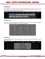
Страница 103: ...et system settings to factory defaults SYSTEM STATUS When selected the Viewfinder output s will display the System Status screen This screen provides a summary of all operational settings currently applied to the camera SYSTEM INFO When selected the Viewfinder output s will display the camera Model current firmware Version installed and camera P I N Version 1 4 0 SVN 29352 BETA 102 102 2011 RED CO...

Страница 104: ...ETED If media is not attached to the camera when attempting to perform a write log request external monitors will display NO MEDIA ATTACHED SW UPDATE Update SW initiates a camera software firmware update If a software update is on the attached media you will be given the option to upgrade the camera For complete detailed procedure go to APPENDIX A UPDATING CAMERA FIRMWARE CALIBRATION Allows you to...

Страница 105: ...libration A status screen will appear showing progress in percent 4 When the Light Shading calibration is complete CALIBRATION SUCCESSFUL is displayed Select OK LIGHT F24 When selected a screen will appear asking if you wish to proceed with F24 Light Shading calibration F24 Light Shading calibration procedure 1 Ensure the sensor is exposed to the F24 calibration light source 2 Ensure a properly fo...

Страница 106: ...hading calibration Black Shading calibration procedure 1 Ensure the lens cap is securely covering the sensor preventing entry of any light source 2 Ensure a properly formatted SSD is attached to the camera and properly formatted 3 Select OK to perform the Black Shading calibration A status screen will appear showing progress in percent 4 When the Black Shading calibration is complete CALIBRATION S...

Страница 107: ...erly formatted SSD is attached to the camera and properly formatted 3 Select OK to perform the Calibrate Apply procedure A status screen will appear showing progress in percent 4 When the Calibrate Apply procedure is complete CALIBRATION COMPLETE will be displayed Select OK NOTE If the Calibrate Apply procedure fails APPLY CALIBRATION FAILED TRY AGAIN will be displayed Perform the APPLY CALIBRATIO...

Страница 108: ...s the sensor test pattern White Screen To turn on select ENABLE SENSOR TEST PATTERN To turn off select DISABLE SENSOR TEST PATTERN TOUCHSCREEN When selected allows you to perform a touchscreen self test Version 1 4 0 SVN 29352 BETA 107 APRIL 19 2011 2011 RED COM INC ...

Страница 109: ...ss the Menu button on the Side Handle or REDmote RESTORE SYSTEM Restore System permits ALL camera configuration and setup data to be reset to factory default values When selected you will be asked to confirm if you want to delete all settings and restore the factory default settings After settings are restored DEFAULT SETTINGS RESTORED INITIALIZING RESTART Camera will automatically power down and ...

Страница 110: ...ways to properly power down your RED EPIC refer to BASIC OPERATION POWER DOWN 1 Press the MENU icon in the right corner of the Upper Status Bar to reveal the Secondary Menus 2 Press POWER from this menu bar 3 Press SHUTDOWN The camera will immediately power down Version 1 4 0 SVN 29352 BETA 109 APRIL 19 2011 2011 RED COM INC ...

Страница 111: ...r number reflects a later release Make a habit of frequently visiting www RED com support to check for later versions of camera firmware Operations Guide updates and postproduction software VERIFY CURRENT CAMERA FIRMWARE With the camera ON select ADVANCED MENU SETTINGS MAINTENANCE SYSTEM INFO The camera s P I N number and current firmware version will be displayed on the Viewfinder output s Versio...

Страница 112: ...load starts you will be prompted to enter your account and password or the camera s P I N 3 After downloading the build you will see the new compressed zipped folder on your desktop 4 Open the new compressed folder and note 2 folders one for Windows it will be the same name as the compressed folder and one for Macintosh OS X _MACOSX Version 1 4 0 SVN 29352 BETA 111 APRIL 19 2011 2011 RED COM INC ...

Страница 113: ... a REDVOLT battery is installed in the side handle remove the battery before upgrading 9 There are two 2 different ways to upgrade camera firmware One while the camera is already on the second requires turning the camera off A To upgrade the camera firmware with the camera ON go to STEP 10 B To upgrade the camera by turning off go to STEP 12 10 With the camera on insert the REDMAG 1 8 SSD into the...

Страница 114: ...S DO NOT POWER DOWN DURING THE PROCESS The progress of the upgrade is displayed in percentage below 16 After the upgrade completes all monitor outputs will display FIRMWARE UPGRADE SOFTWARE UPGRADE SUCCESSFUL PLEASE RE START THE CAMERA 17 Power the camera down and back up 18 Perform a Dark Shading Calibration Refer to SECONDARY MENUS SETTINGS MAINTENANCE CALIBRATION for complete information Versio...

Страница 115: ...camera to just add the necessary project profile and clip log data NOTE Media formatted on camera will use a name and root volume in the format Camera Letter Reel Number Month Day where is a two digit alphanumeric random number generated by the camera for each file e g A001_0512A6 RDM Clips recorded to the media follow similar naming conventions A001_C001_0512A6_001 RDC and A001_C001_0512A6_H mov ...

Страница 116: ...G NOTE If when selecting FORMAT the display indicates FORMAT FAILED refer to MEDIA ERRORS 4 Once formatting is completed the Viewfinder output s will display THE MAGAZINE WAS SUCCESSFULLY FORMATTED THE DIGTAL MAGAZINE IS READY FOR IMMEDIATE USE MEDIA CAPACITY REMAINING STATUS The Viewfinder output s will display the remaining media capacity in the MEDIA indicator 100 is shown At 10 remaining capac...

Страница 117: ...tegrity of your recorded data and helps clips mount instantly to your workstation once in postproduction so it s a recommended habit to develop If you do not un mount the media the camera will offer a warning your files may not be damaged but you will have been warned NOTE The camera will respond to physical removal of the media without un mounting and display MEDIA REMOVED PRIOR TO UNMOUNT DATA I...

Страница 118: ...edia is ejected Viewfinder output s will display MEDIA EJECTED SUCCESSFULLY 3 Media can now be removed from the camera COPYING MEDIA For use when media is connected directly to your computer When copying media it is recommended that you drag the complete RDM folder on the digital magazine to the archive storage media This copies all the media and metadata files You will not need to copy the log ma...

Страница 119: ...ect it 8 The media will need to be formatting by the camera before use Refer to FORMATTING WINDOWS 1 Connect the REDMAG 1 8 SSD via RED STATION REDMAG 1 8 2 Open Windows Explorer go to my computer icon right click and select EXPLORE 3 Double click on the dive you wish to erase files from 4 Select all the files on the drive you wish to erase IMPORTANT Before performing the next step double check th...

Страница 120: ...nutes 1 Plug the supplied AC power cord into the charger s AC input and then into the AC power source 2 Verify that the charger s LED status bar is solid Red indicating ready to receive battery for charging 3 Insert a REDVOLT battery into the charger 4 Leave the battery to charge for the appropriate time as shown in the table assuming battery is discharged completely Charger status LED flashes Ora...

Страница 121: ...APPENDIX D INPUT OUTPUT CONNECTORS BRAIN FRONT A MIC 1 3 5mm Audio Jack B MIC 2 3 5mm Audio Jack B A Figure18 Brain Connectors Front Version 1 4 0 SVN 29352 BETA 120 120 2011 RED COM INC APRIL 19 2011 ...

Страница 122: ...ls are routed via a high quality A D and pre amplifier whose Gain may be controlled using the Input Level control to achieve the desired audio reference recording level Each microphone input supports 48V 10mA Phantom Power as a user selectable option To assist with reference level setup the camera provides a color coded Peak Level Meter in the Graphical User Interface with a solid vertical witness...

Страница 123: ...B C D E F G A HD SDI B Headphone C SYNC Video Sync D CTRL RS232 Control E GIG E Ethernet F DC IN Power Input G HDMI Figure 20 Brain Connectors Rear Version 1 4 0 SVN 29352 BETA 122 122 2011 RED COM INC APRIL 19 2011 ...

Страница 124: ...en in 3GHz HD SDI mode The HD SDI output may be specified as a PROGRAM output clean feed video or as a PREVIEW output with SurroundView look around Clip Name Timecode and Safe Action Safe Title frame guides In addition to video data the HD SDI output also provides two 2 channels of embedded audio Time of Day timecode record tally flag and Clip Name information as SMPTE RP 188 VITC2 HANC metadata N...

Страница 125: ... ground The camera s four audio channels may be monitored in pairs either 1L 2R or 3L 4 R or as a quad mix of 1 3L 2 4R based on the MIX parameter Default is 1L 2R Output volume may be adjusted as follows Volume master volume Adjusts headphone volume equally for left and right outputs Range is 18dB to 0dB in 1dB steps Default is 9dB NOTE for maximum output signal quality only use high impedance he...

Страница 126: ...r each frame of recorded video A Video Genlock input signal may be used as a vertical interval reference signal for applications that require precise synchronization between cameras such as 3D and live broadcasts When using GENLOCK as the camera shutter timing reference fine shutter start time timing SHUTTER PHASE may be adjusted Figure 22 View into camera SYNC Video Sync Interface connector Matin...

Страница 127: ...pre fabricated SYNC interface cable is available from RED Digital Cinema x Part 140 0078 Video Sync Camera to 3 BNC 3 ft 1m x White BNC Shutter Sync GPI x Yellow BNC SMPTE Timecode x Green BNC RS170A Genlock Version 1 4 0 SVN 29352 BETA 126 126 2011 RED COM INC APRIL 19 2011 ...

Страница 128: ...device needs to be synchronized to a master camera Alternatively this output pin may be used as a GPO General Purpose Output tally whose function is programmed in the USER KEYS menu Default is Record Tally Pin Signal Description 1 GROUND Common Ground 2 232 RX RS232 RX 3 SS GPO Shutter Sync GPO Output 4 232 TX RS232 TX NOTE When active the GPO tally presents 3 3V 0 04 Amps maximum between pins 1 a...

Страница 129: ...GG 0B 309 CLAD32Z Pin Signal Description Direction 1 B1_DC Data Pair C 2 B1_DC Data Pair C 3 B1_DD Data Pair D 4 B1_DD Data Pair D 5 B1_DA Data Pair A 6 B1_DA Data Pair A 7 B1_DB Data Pair B 8 B1_DB Data Pair B 9 Do Not Connect NOTE Two pre fabricated Ethernet interface cables are available from RED Digital Cinema x Part 140 0152 Ethernet Camera to Camera 3 ft 1m x Part 140 0125 Ethernet Camera to...

Страница 130: ...ery Bus Clock 4 GROUND Power Return Camera Ground 5 6 SCA BATT Serial Battery Bus Data WARNING It is very important that both pairs of VBATT and GROUND pins are wired up DO NOT fabricate power cables with just one each of VBATT and GROUND pins wired as this may cause damage to the camera s power supply this is not covered by Warranty NOTE Two pre fabricated DC Power input cables are available from...

Страница 131: ...t clean feed video or as a PREVIEW output with SurroundView look around Clip Name Timecode and Safe Action Safe Title frame guides In addition to video data the HD SDI output also provides 4 channels of embedded audio NOTE Default setting is PREVIEW NOTE HDMI video output is Progressive Scan it does not support 1080i or 1080PsF modes Version 1 4 0 SVN 29352 BETA 130 130 2011 RED COM INC APRIL 19 2...

Страница 132: ...output Module o the front face of the Side SSD provides digital video communications and power interconnection between the camera and a RED EVF or RED LCD digital display Due to the requirement for absolute data integrity this requires a custom cable manufactured by RED the pin out of this interface is not published NOTE Pre fabricated VIEWFINDER cables are available from RED Digital Cinema x Part...

Страница 133: ...to charge the REDmote from a 3rd party USB power source The REDmote interface connector B allows communication between the REDmote and the EPIC or SCARLET Brain or any expansion module when installed Make sure these contacts are kept clean and free of any grease that may interfere with electrical contact Version 1 4 0 SVN 29352 BETA 132 132 2011 RED COM INC APRIL 19 2011 ...

Страница 134: ...se Button R E Zoom Rocker Switch J Focus Record Button O USB Power Port C D A B E G F H J I O N K L M STILL MOTION TOGGLE SWITCH On the upper left edge of the REDmote is the STILLS MOVIE toggle switch A used to switch between STILLS operation DOWN and MOVIE operation UP The toggle switch is set to the MOVIE position the camera settings and defaults become movie specific When the toggle switch is s...

Страница 135: ...cus Indicator x User Key B Enables White Balance calculation x User Key C Enables 1 1 Focus Check x User Key D Enables false color Exposure Check MENU BUTTON Below and to the left of the User Keys is the MENU button G press once enter the menus at the top level press twice in quick succession to re enter menus at the last location from which you exited them SOFT MENU BUTTONS 1 3 Below the LCD are ...

Страница 136: ...he center allows confirmation of a parameter adjustment FOCUS AND RECORD BUTTON Below the Navigation Group is the focus and record button J This is a dual throw action switch A half press initiates Auto Focus a full press initiates still capture or starts stops a movie recording When recording the upper LED will illuminate Red and a Red dot will appear to the immediate left of the Timecode on the ...

Страница 137: ...NNECTOR for complete information CHARGING BATTERY LIFE CHARGING USING CAMERA While connected to the camera the REDmote will automatically recharge its internal battery Charge status is indicated by the Green Battery Icon at the top right of the REDmote LCD display screen A fully discharged REDmote battery will be re charged in approximately 8 hours if connected to a powered camera A much faster ch...

Страница 138: ...er of the screen same indicator as charge but without the lightning bolt When battery life is good indicator is Green when battery life is marginal indicator will be Yellow When battery life becomes low and requires recharging the indicator turns Red WIRELESS OPERATION BATTERY LIFE When using the REDmote in a wireless configuration the battery will last approximately 8 hours before charging is nec...

Страница 139: ...he REDmote is securely attached NOTE If the camera is ON the REDmote will automatically power UP when connected REMOVING UNDOCKING 1 Depress the two 2 release buttons located on the sides of the REDmote 2 Slide the REDmote upward to release from the V Mount of the camera module 3 Remove the REDmote Version 1 4 0 SVN 29352 BETA 138 138 2011 RED COM INC APRIL 19 2011 ...

Страница 140: ...connect REDmote to the camera 4 The REDmote LCD screen will then return to a similar Status Screen as seen when physically attached to the camera you can operate the camera using the REDmote via the REDlink 2 4GHz wireless link The wireless indicator showing signal strength will be displayed in the upper left corner of the REDmote display 5 Once the REDmote has communicated with a camera it does n...

Страница 141: ...ally powered down using the Power Lock Switch NOT CONNECTED TO CAMERA To manually power DOWN the REDmote Press and hold the Power Lock Switch in the Down direction for 2 seconds then release RECORDING IMPORTANT Before recording from a REDmote ensure the camera is properly powered set up and media is connected Refer to BASIC OPERATION To record press the Red REC record button on the REDmote x If me...

Страница 142: ... select that parameter and use the Scroll Wheel to adjust that parameter s value To confirm the change in parameter value and to exit the adjustment menu press the ENTER button To access the camera s menus press the MENU button at the lower left The MENU displays on the EVF LCD or external monitors if the LCD and or EVF are not connected disconnected Use the NAV GROUP to make changes to the camera...

Страница 143: ...APPENDIX F 3D SETUP OPERATION This section under construction Version 1 4 0 SVN 29352 BETA 142 142 2011 RED COM INC APRIL 19 2011 ...

Страница 144: ...ose of elements in deep shadow which may therefore be prone to noise when developed in post production The following reference scene includes highlight and shadow elements and was shot at ISO 800 UNDEREXPOSURE 2 STOPS ISO 800 Monitor Output In the image above it is obvious the camera is under exposed The initial clues are the monitor is very dark and the histogram is justified to the left Also not...

Страница 145: ...mode allows us to visualize where in the image underexposure is taking place These areas are indicated in purple It is clear those areas are under the matchbox and coin and between the bottle and cigar holder ISO 800 False Color Video Version 1 4 0 SVN 29352 BETA 144 144 2011 RED COM INC APRIL 19 2011 ...

Страница 146: ...the shadow information will probably display with significant noise once pushed to an acceptable brightness OVEREXPOSURE 2 STOPS ISO 800 Monitor Output In the image above it is obvious the camera is over exposed The monitor is very bright and the histogram is justified to the right Note the red bar at the right edge of the histogram and the vertical color stack to the right of the histogram is sho...

Страница 147: ...ive This mode allows us to visualize where in the image over exposure is taking place These areas are indicated in red It is clear those areas are on the highlight on coin and at the top right edge of the color chip test chart Version 1 4 0 SVN 29352 BETA 146 146 2011 RED COM INC APRIL 19 2011 ...

Страница 148: ...a significant portion of the monitor path video is at the maximum legal 100 IRE value Because the scene is over exposed when the recorded R3D file is color corrected in post production the scene s highlight information will almost certainly be clipped however the shadow information will probably display cleanly once pulled back down to an acceptable brightness Version 1 4 0 SVN 29352 BETA 147 APRI...

Страница 149: ...in we wish not to blow out Note that there is no red bar on either the left or the right edges of the histogram and the vertical color stack to the right of the histogram is at yellow These indicators suggest that there is no significant amount of the sensor s RAW data in the noise or at clip and that the peak level of the sensor s RAW data is about 2 3 stop below clipping Version 1 4 0 SVN 29352 ...

Страница 150: ...re there is under exposure purple or over exposure red in the image In this case there is a very small area of purple under the cracker box and just a suggestion of red on the highlight on the coin which suggested that the sensor is appropriately exposed for this scene Version 1 4 0 SVN 29352 BETA 149 APRIL 19 2011 2011 RED COM INC ...

Страница 151: ... grey and skin tone elements plus peak white and blacks are all at appropriate levels Because the scene was well exposed when the recorded clip is color corrected in post production sufficient headroom exists for the scene s highlight information to be displayed without clipping and the shadow information can be displayed without significant noise even if the brightness of the shadow information i...

Страница 152: ...then to ISO 100 Note the although the image and Histogram both adjust to changes in the ISO rating the sensor RAW meters do not change they always indicate what s happening at the sensor level and hence where the image is truly in noise or at clipping ISO 6400 No Exposure Adjustment Version 1 4 0 SVN 29352 BETA 151 APRIL 19 2011 2011 RED COM INC ...

Страница 153: ... be reducing exposure at the sensor this biases exposure in favor of protecting the scene highlight Alternatively if you choose to open the iris to increase the brightness of the image of the second image you will be increasing exposure at the sensor this biases exposure in favor of minimizing noise in the scene shadows The technique is similar in principle to re rating a film stock With practice ...

Страница 154: ...ic one light image processing and color correction Using REDCINE X footage can also be cropped resized or repositioned These functions lessen the amount of time required for color correction or re framing of shots after the final cut has been completed REDCINE X can also encode 4K or 2K RAW footage into a variety of uncompressed RGB and compressed 4 2 2 video formats Provided the appropriate Quick...

Страница 155: ...CINE X provides image pan scan crop and scaling operations The application can export either a single clip or a sequence of clips as 4K or 2K resolution 10 bit DPX or 16 bit TIFF files REDCINE X can also render clips into standalone QuickTime movies using specific HD video codecs As RED EPIC shoots progressive scan images all QuickTime movies created by REDCINE X are also progressive scan REDCINE ...

Страница 156: ...y is installed remove the battery and perform the upgrade procedure again APPLY CALIBRATION FAILED If the Calibrate Apply procedure fails APPLY CALIBRATION FAILED TRY AGAIN will be displayed Perform the APPLY CALIBRATION procedure again RECORDING HALTED RECORD ERROR SHUTDOWN Displayed if media removed while recording DO NOT remove media while camera is recording Power down the camera verify the me...

Страница 157: ... If this message appears perform the following x Check power sources for low voltage or brown out spikes x Check for proper grounding of outlets for power supplies Version 1 4 0 SVN 29352 BETA 156 156 2011 RED COM INC APRIL 19 2011 ...

Страница 158: ...an ONLY using a dry cloth When cleaning your camera and accessories remember that it is not waterproof and moisture can damage electronic circuitry BRAIN SENSOR Use Delkin Devices Digital Duster Kit Part No DDSS DUSTER2 or equivalent to clean sensor surface OPTICAL LOW PASS FILTER OLPF If equipped with an OLPF use Delkin Devices Digital Duster Kit Part No DDSS DUSTER2 or equivalent to clean OLPF s...

Страница 159: ...ographic Solutions Pac Pads Part No 05011 or equivalent to clean the viewfinder lens Ensure your spray the solution onto the pad and not directly onto the lens surface SIDE HANDLE LCD Use Pancro Professional Lens Cleaner Part No PANCROCLN and Photographic Solutions Pac Pads Part No 05011 or equivalent to clean the screen on the Side Handle LCD ELECTRICAL CONTACTS This section under construction Ve...

Страница 160: ...RAM OUTPUT x x x HD SDI Clean Feed 2K RGB 1080p RGB or 4 2 2 720p 4 2 2 SMPTE Timecode HANC Metadata 24 bit 48Khz Audio MONITOR OUTPUT x x x HD SDI and HDMI with Frame Guides and Look Around 2K RGB 1080p RGB or 4 2 2 720p RGB or 4 2 2 SMPTE Timecode HANC Metadata 24 bit 48Khz Audio DIGITAL MEDIA x REDMAG 1 8 SSD Module 64 128 256GB Media REDCODE x x x x 12 and 16 bit RAW RC25 250 Quality Levels 1 ...

Страница 161: ...BRAIN DIMENSIONS FRONT VIEW Version 1 4 0 SVN 29352 BETA 160 160 2011 RED COM INC APRIL 19 2011 ...

Страница 162: ...SIDE VIEW Version 1 4 0 SVN 29352 BETA 161 APRIL 19 2011 2011 RED COM INC ...

Страница 163: ...TOP VIEW Version 1 4 0 SVN 29352 BETA 162 162 2011 RED COM INC APRIL 19 2011 ...

Страница 164: ...1 700 to 10 000 K BASIC 5K 2 1 5K 2 1 5K FF 5K 2 4 1 8 1 2 1 to 18 1 SECONDARY MENUSPRESS MENU ICON LCD OR MENU BUTTON TO ACCESS FOCUS EXPOSURE PRESETS POWER HDR MEDIA SETTTINGS SHUTDOWN POWERS DOWN CAMERA OFF HDRx OFF HDRx HDRx ON PRESETS USER DEFINED PRESETS CREATE IMPORT EXPORT DELETE NEW PRESET EXISTING Image Project Output System Keys SELECT VALUES SHADE DAYLIGHT TUNGSTEN DISK PRESETS SELECT ...

Страница 165: ...E CODE TOD EDGE TOD GUI SKIN NORMAL OUTDOOR NIGHT Normal EXPOSURE TIME ANGLE Time APERTURE 1 4 F 1 3 F 1 3 F SIZE OFF FULL 2 4 1 Off TRANSPARENCY 0 25 50 75 100 50 1 9 1 USER 1 85 1 16 9 4 3 COLOR WHITE GRAY TEAL White BLUE RED BLACK PURPLE YELLOW GREEN USER ASPECT RATIO 1 00 TO 10 00 2 40 1 0 1 00 TO 10 00 USER SCALE X Y 0 0 TO 100 0 100 0 100 0 0 0 TO 100 0 ASPECT RATIO OFF 16 9 14 9 Off TRANSPA...

Страница 166: ... EXTERNAL TC INT USER PROVIDED TC Ext Analog TC In TIME BASE TIME CODE 0 TO 23 0 AATON SERIAL 0 TO 59 0 SET MANUALLY 0 TO 59 0 RTC TIME USER TC SECONDARY MENUSPRESS MENU ICON LCD OR MENU BUTTON TO ACCESS GO TO SHEET 1 OF 4 47 96 48 00 50 00 59 94 KEYS DATE TIME NETWORK SERIAL REMOTE GPIO SYSTEM USER A AF Mode USER B WB Calc USER C Toggle Magnify USER D Exposure Check USER DATE M D Y TIME H M S ENT...

Страница 167: ...GHT SHADING CALIBRATION PROMPTS TO PERFORM BLACK SHADING CALIBRATION PROMPTS TO PERFORM CALIBRATE APPLY CALIBRATION ENABLES TOUCHSCREEN TEST TO EXIT TAP AND HOLD TOUCHSCREEN PROMPTS TO RESTORE TO FACTORY SETTINGS REQUIRES REBOOT OF CAMERA MEDIA SETTTINGS DEFAULT VALUES ARE DISPLAYED IN BOXES FLOWCHART CONCEPT XL FILMS LTD GO TO SHEET 3 OF 4 SYS TATUS SYS S INFO SAVE LOG SW U CALIB PDATE SELF RATIO...

Страница 168: ......

Отзывы: