REC ACTIVE BMS 4S
10
www.rec-bms.com
Balancing START Voltage:
If errors 2, 4, 5, 8, 10, 12 are not present, highest cell voltage rises above Balancing START voltage and current is >
0.2 A (charging stage) the BMS initiates balancing algorithm. A weighted cell voltage average is determined
including cells DC internal resistance. Balancing algorithm calculates the voltage above which the cells are balanced.
The lowest cell voltage is taken into account determining balancing voltage.
Balancing END Voltage:
If errors 2, 4, 5, 8, 10, 12 are not present, the cells above balancing END voltage are balanced regardless the battery
pack current.
Cell Internal DC Resistance Measurement:
Cell internal DC resistance is measured as a ratio of a voltage change and current change in two sequential
measurement cycles. If the absolute current change is above 20 A, cells internal resistance is calculated. Moving
average is used to filter out voltage spikes errors.
Battery Pack Temperature Measurement:
Battery pack temperatures are measured by Dallas DS18B20 digital temperature sensors. Up to eight sensors can
be used in parallel. BMS should be turned off before adding additional sensors. If the temperature sensors wiring
is placed near the power lines shielded cables should be used.
BMS Current Measurement:
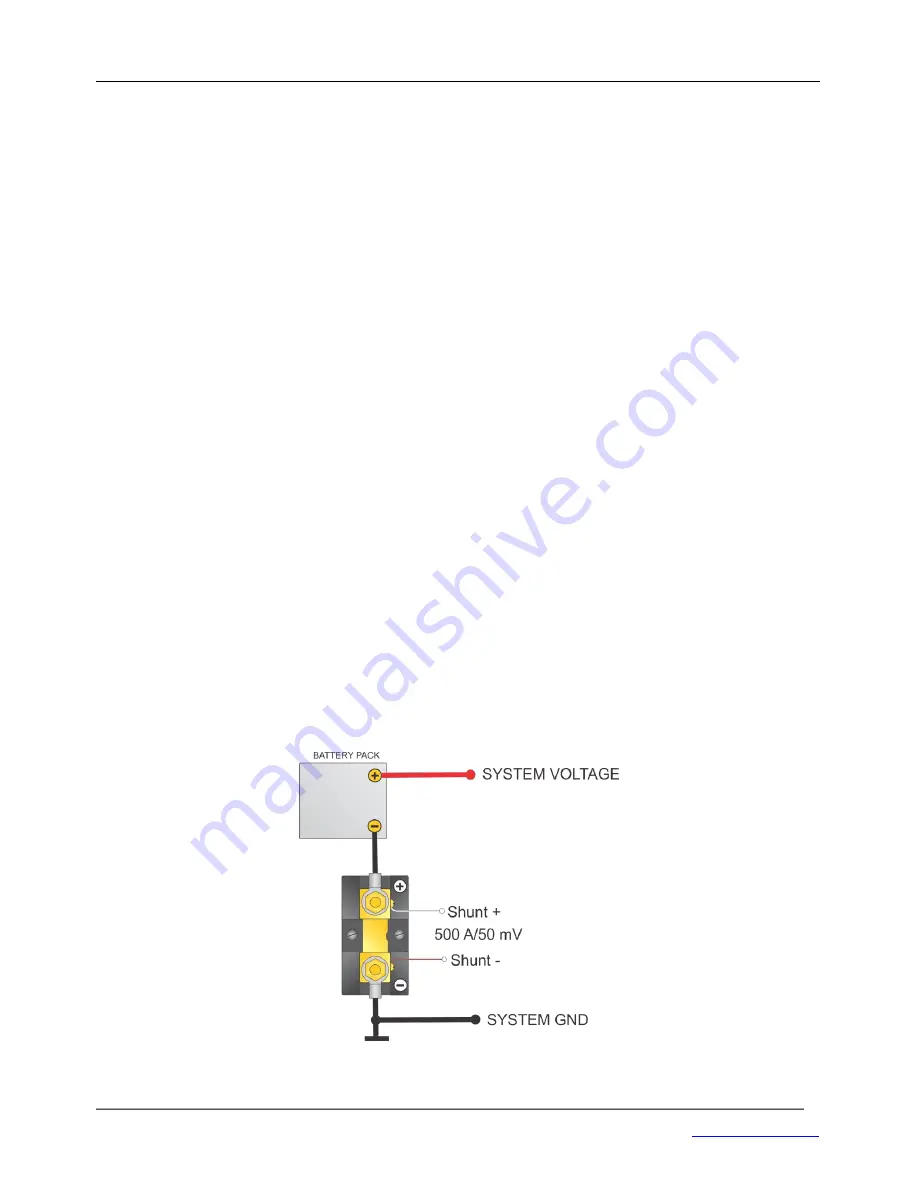
A low-side precision shunt resistor for current measurement is used. A 4-wire Kelvin connection is used to measure
the voltage drop on the resistor. As short as possible
shielded cable
should be used to connect the power shunt
and BMS. The battery pack current is measured every second. A high precision ADC is used to filter out the current
spikes. The first current measurement is timed at the beginning of the cell measurement procedure for a proper
internal DC resistance calculation. Shunt connection is shown in Fig. 6.
Figure 6:
Shunt resistor connection.


