background image

VREngine/SMD Series Users Manual 


RealVision Inc.

 16 


The installer tries to match each connected monitor with its list of known monitor 
types. If it succeeds, it skips directly to the Start Copying Files dialog in 

Fig. 14

. If 

it cannot match one or more monitors, the Monitor selection dialog will appear. 
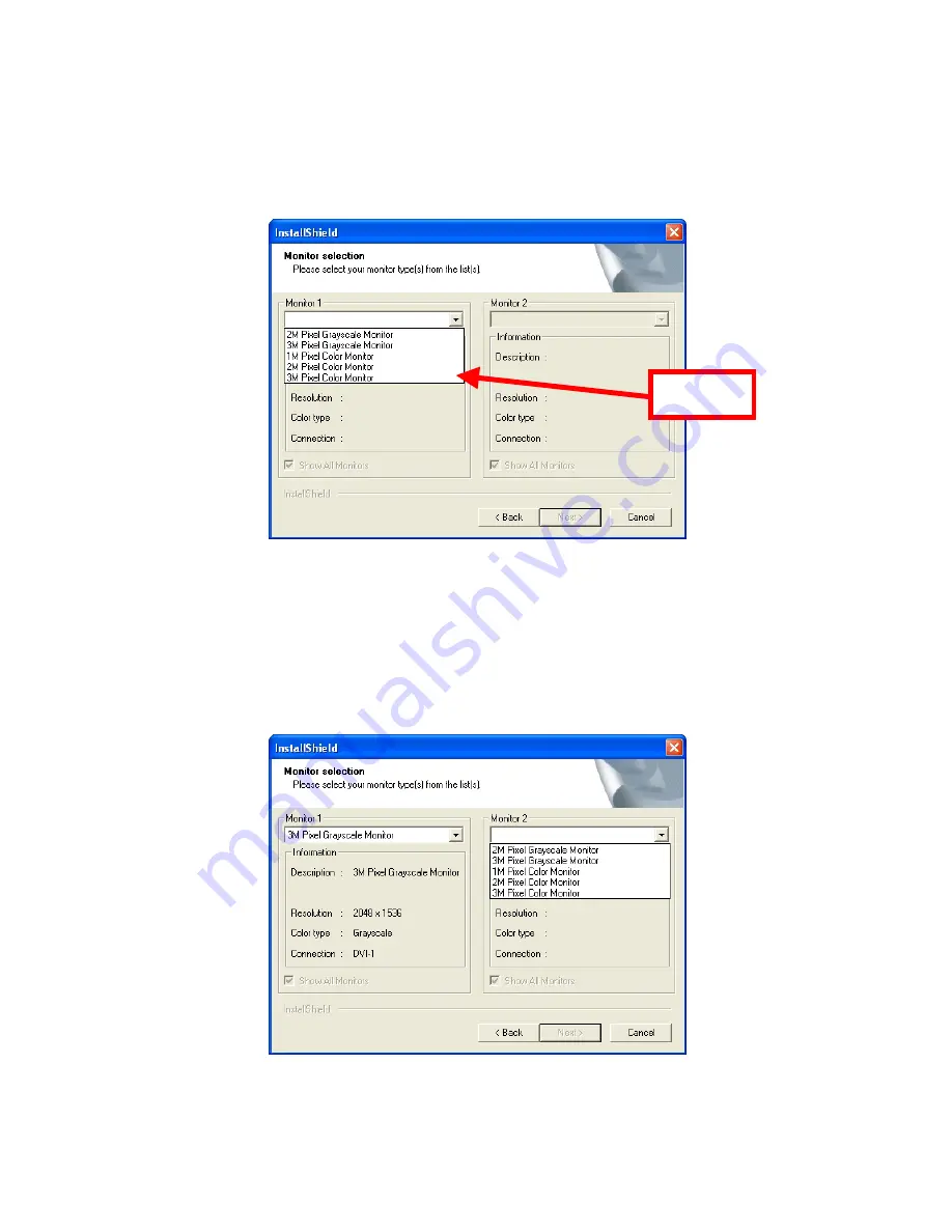
Select the type of Monitor 1 from the list

.


Select 

Fig. 11

 Monitor selection dialog 

N.B. 

If a monitor has been partly identified, a subset of the list may be displayed. You 

can force the complete list to be displayed by selecting “Show All Monitors”. 


If there are 2 monitors connected to the board, repeat the selection process for 
Monitor 2. 


Fig. 12

 Selection of second monitor type 

Содержание VREngine/SMD2-PCI

Страница 1: ...Document No 6100084 03 VREngineTM SMD Series High Resolution Graphics Board User s Manual Manual version 3 1b RealVision Inc ...

Страница 2: ...rect the interference by one or more of the following measures Reorient or relocate the radio or television receiving antenna Move the computer or equipment away from the receiver Plug the computer or equipment into an outlet on a circuit different from that which the radio or television receiver is connected Consult the dealer or an experienced radio TV technician for help CE Statement This is Cl...

Страница 3: ...REngineTM SMD Series High Resolution Graphics Board User s Manual version 3 1b RealVision Inc 3 1 1 Shin Yokohama Kōhoku ku Kanagawa 222 8505 Japan Tel 81 45 473 7331 Fax 81 45 471 7330 http www realvision co jp http www rvu inc com All rights reserved ...

Страница 4: ...link 3 megapixel grayscale and color LCD monitors VREngine SMD5 PCI Graphics board for single link 2 3 and 5 megapixel grayscale and color LCD monitors For information regarding LCD monitors or related matters please contact your vendor or display manufacturer About This Manual Please read through this manual before you install or use your VREngine SMD Series board This manual provides detailed in...

Страница 5: ...ealVision Inc All other trademarks are the property of their respective owners Safety precautions This product is manufactured with all due care but failure to exercise care during or incorrect operation may lead to accidents In order to avoid such problems please use the product only after reading and understanding this manual thoroughly ...

Страница 6: ...11 4 Installing the Driver Software 12 5 Monitor And Display Settings 20 5 1 Display Properties 20 5 1 1 Color quality settings 23 5 1 2 Screen resolution settings 23 5 2 VREngine advanced settings 24 5 2 1 Color Palette settings 26 5 2 2 Screen Update settings 27 5 3 Multi Monitor settings 28 5 4 Detailed display adaptor and driver information 37 5 5 Monitor reconfiguration driver update and unin...

Страница 7: ...n case you need to return the board to your supplier for any reason Shipping damage is not covered under the warranty 2 Installation Overview The installation process involves the following steps Configure the board DIP switch settings as required Install the board into the host system Connect the LCD monitor s to the DVI outputs Power on the host system Manually install the driver software Reboot...

Страница 8: ...tacts or bent connector pins and no rubbish or dirt fouling the connectors Use of broken pins or dirty cables could result in a short circuit leading to fire Take care not to break the connectors by dropping them on the floor or elsewhere and not to drag cables on the floor or do anything else that might damage them or make them dirty Fasten connector lock screws tightly and take care not to drop ...

Страница 9: ... 2 With these settings the VGA signal is automatically determined using the EDID data read from the monitor during initialization Fig 2 VGA output setting for an EDID compatible monitor 3 3 Inserting the board 1 Ensure that your computer and any peripheral devices connected to it are completely turned off N B The internal parts of your computer are still very hot just after being turned off Wait u...

Страница 10: ...e Confirm that the board appears to be seated properly N B If the board is not properly seated you should remove it from the slot completely and insert it again from scratch Do not use excessive force to insert or remove the board to avoid damage to the cables connectors or the board itself PCI X Bus slot PCI X Bus slot PCI X Bus slot 33MHz PCI Bus slot 33MHz PCI Bus slot AGP Bus slot Fig 3 Host s...

Страница 11: ...nnector 1 nearest the PCI Bus connector If you use DVI Connector 2 no image will be displayed Fig 4 Board connected to one monitor Connecting a board to two monitors The driver settings allow a great deal of flexibility in monitor arrangement see page 28 but for simplest operation connect the left hand monitor to DVI Connector 1 nearest the PCI Bus connector and the right hand monitor to DVI Conne...

Страница 12: ...ver The Found New Hardware Wizard dialog will appear Click the Cancel button The dialog will be displayed once for each newly installed board N B It is important that you do not allow the Found New Hardware Wizard to install the driver automatically Fig 6 Found New Hardware Wizard dialog Insert the VREngine SMD Driver CD ROM into your CD ROM drive The driver installation wizard should start automa...

Страница 13: ...me dialog will appear Click the Next button Fig 7 InstallShield Wizard welcome dialog The License Agreement dialog box will appear Review the license terms and click the Yes button if you accept them If you click the No button the installation will terminate Fig 8 License Agreement ...

Страница 14: ...VREngine SMD Series Users Manual RealVision Inc 14 One of the following two dialog boxes will appear Confirm the number of boards detected and click the OK button Fig 9 Board detection dialogs ...

Страница 15: ...nc 15 The Number of monitors dialog in Fig 10 will appear Confirm the board type has been correctly detected select the number of monitors connected to the board and click the Next button Check Select Click Fig 10 Select number of monitors dialog ...

Страница 16: ...h one or more monitors the Monitor selection dialog will appear Select the type of Monitor 1 from the list Select Fig 11 Monitor selection dialog N B If a monitor has been partly identified a subset of the list may be displayed You can force the complete list to be displayed by selecting Show All Monitors If there are 2 monitors connected to the board repeat the selection process for Monitor 2 Fig...

Страница 17: ... Next button to proceed Check Fig 13 Confirm selected monitor type s If you have installed 2 VREngine SMD graphics boards the Number of monitors and Monitor selection dialogs are displayed once for each board Repeat the steps above for the second board N B The list of available monitors varies from vendor to vendor and may not match the above illustrations exactly ...

Страница 18: ... driver is not digitally signed under the Windows Logo testing program Click on the Continue Anyway button to proceed The dialog will appear once for each VREngine SMD graphics board Fig 15 Windows XP Windows Logo warning dialog On Windows 2000 the Digital Signature Not Found dialog is displayed once for each monitor rather than once for each board Click the Yes button to continue the installation...

Страница 19: ...restart my computer now and click the Finish button You must reboot before you can peform the final stages of configuration Fig 17 InstallShield Wizard Complete dialog N B If you add additional boards or move a board to a different PCI slot you must un install and reinstall the driver software from scratch When multiple graphics boards are installed the BIOS on some motherboards may fail to boot c...

Страница 20: ...te 5 1 Display Properties Open the Display Properties control panel Choose Control Panel from the Start menu and double click on Display Fig 18 Control Panel If the Control Panel is in Category View click on Appearance and Themes then click on Display in the sub list of control panels or click on Switch To Classic View to display the full list of available control panels ...

Страница 21: ... 21 You can also right click on any empty part of your desktop and select Properties from the pop up menu to show the Display Properties panel Click the Settings tab to display the dialog shown in Fig 20 Fig 19 Display Properties Fig 20 Settings tab ...

Страница 22: ...r for the VREngine SMD board has been installed but the board is not yet configured The connected monitor displays nothing and the monitor icon in the Settings tab is grayed out If there is no other display adaptor and only one VREngine SMD series board is installed there will be no 2nd display icon and the 1st monitor icon will be the monitor connected to VREngine SMD Series board Click the appro...

Страница 23: ... 8 bit grayscale modes you can select only Low 8 bit In 10 bit grayscale modes you can select only Medium 16 bit 5 1 2 Screen resolution settings When using a color monitor or a grayscale monitor in 24 bit color conversion grayscale mode you can select the desired resolution using the Screen resolution slider as normal When using the 8 bit grayscale modes under Windows XP the Screen resolution sli...

Страница 24: ...es Users Manual RealVision Inc 24 5 2 VREngine advanced settings Click on the Advanced button in the Display Properties dialog to display the Monitor and Adaptor Advanced Settings dialog Fig 23 Advanced Settings dialog ...

Страница 25: ... checkbox will be enabled When it is checked you can modify the Mode settings for all the monitors at the same time Multi Monitor Settings Click this button to access the Multi Monitor settings control panel See page 28 When using multiple monitors unless the Apply to all displays checkbox is enabled you must return to the Display Properties dialog and select each monitor in turn to configure it N...

Страница 26: ... and makes a linear palette of the remaining 236 entries 8 bit dynamic grayscale palette Allows the palette to be dynamically controlled by other programs 8 16 24 bit color The standard windows color quality Highest 32 bit and Medium 16 bit settings are available in the Display Properties dialog 10 bit grayscale 1024 shades of gray 24 bit color conversion grayscale In this mode VREngine SMD board ...

Страница 27: ...d quality of display High speed Updates the screen in blocks for fastest drawing With some applications you may experience staircase shaped after images If this is a problem please select another mode Standard Attempts a trade off between high speed and high quality High quality Updates the whole screen at once Provides the smoothest slowest display with no after images ...

Страница 28: ...el Choose Control Panel from the Start menu and double click on VREngine MD Series Fig 27 Control Panel If the Control Panel is in Category View click on Appearance and Themes then click on Display in the sub list of control panels or click on Switch To Classic View to display the full list of available control panels ...

Страница 29: ...his dialog shows an example with one VREngine SMD Series board and 2 monitors installed in the All Independent setting Fig 28 Multi Monitor tab Each monitor connected to a VREngine SMD Series board is given a letter in sequence A B C The numbering scheme in the Display Properties dialog is not used ...

Страница 30: ...dentifying letter of the selected monitor is shown in black Information Fig 29 Monitor Information The following information is displayed Description Shows the monitor type as selected in the installer Resolution The monitor resolution Color type Grayscale or color Connection Shows the VREngine SMD Series board number and monitor number ...

Страница 31: ...he sequence for adding a new monitor to a virtual monitor group is as follows Select a monitor to connect Right click on it to show the monitor connection menu Choose the appropriate connection direction or type Choose the target monitor from the sub menu The selected monitor is connected to the chosen target monitor Fig 30 Monitor connection menu ...

Страница 32: ...the following dialog Fig 31 Two monitors combined Connect to the Right Connect to the Right joins the selected monitor to the right hand side of the target monitor In the following example Display B will be connected to right hand side of Display A creating a single virtual monitor Fig 32 Connect to the Right ...

Страница 33: ...the target monitor In the following example Display B will be connected to bottom of Display A creating a single virtual monitor Fig 33 Connect to the Bottom Clone Clone sets the selected monitor to display a clone of the same image as the target monitor In the following example Display B will mirror the contents of Display A Fig 34 Clone ...

Страница 34: ...lone mode Independent Independent disconnects the selected monitor from its connected monitor s It is not available if the monitor is not connected to any other monitors Fig 36 Independent N B The new settings are stored when you click OK or Apply but are not immediately activated When you change the settings a dialog will appear asking whether you want to reboot your workstation Changes are activ...

Страница 35: ...e provided The supported presets are All Independent Unified and All Unified Fig 37 Multi monitor presets All Independent Click on the All Independent button to use all the monitors connected to VREngine SMD Series boards independently Clicking this button destroys any connections previously made between monitors Fig 38 All Independent ...

Страница 36: ...on destroys any connections previously made between monitors Fig 39 Unified All Unified Click on the All Unified button to group all the monitors connected to VREngine SMD Series boards into one virtual wide monitor Clicking this button destroys any connections previously made between monitors The All Unified button is disabled when there is only one VREngine SMD Series board in the workstation Fi...

Страница 37: ... control panel Choose Control Panel from the Start menu and double click on VREngine MD Series Fig 41 Control Panel If the Control Panel is in Category View click on Appearance and Themes then click on Display in the sub list of control panels or click on Switch To Classic View to display the full list of available control panels ...

Страница 38: ... Manual RealVision Inc 38 A dialog similar to the following will appear Fig 42 Properties tab Click on the Properties tab to display detailed information about the display adaptor s and driver files Fig 43 Detailed Information ...

Страница 39: ...rs Manual RealVision Inc 39 The following information is displayed Display adapter information Shows the product name BIOS version PCI bus location etc Driver information Shows a list of driver files and their version numbers ...

Страница 40: ...tion and click the Next button Reconfigure monitor s Select this option if you want to add new monitors or change existing monitor type settings Update Select this option if you want to update the driver software or add or remove a VREngine SMD Series board from the system The installer uninstalls and reinstalls the software as a single operation For additional information related to installation ...

Страница 41: ...on describes how to uninstall the driver software Choose Control Panel from the Start menu and double click on the Add or Remove Programs icon Fig 45 Control Panel classic view If the Control Panel is in Category View click once on the Add or Remove Programs category Fig 46 Control Panel category view ...

Страница 42: ...splay Driver in the list of Currently installed programs to highlight it Click the Change Remove button The dialog below appears Click Yes to begin the uninstallation process Fig 48 Confirm uninstallation N B You will have to reboot your workstation to complete the uninstallation Before you begin uninstalling terminate all other running applications ...

Страница 43: ...VREngine SMD Series Users Manual RealVision Inc 43 When the following dialog is displayed click Yes to reboot your system and complete the uninstallation Fig 49 Confirm reboot ...

Страница 44: ...bus slot x1 Mechanical Spec of boards PCI board x1 Display Resolution Single monitor 1600 x 1200 pixel Landscape 1200 x 1600 pixel Portrait Connectable Monitors Note 1 2M VESA compliant digital LCD monitors Other 2M digital LCD monitors of connectable monitors Max 2 Display Modes Note 2 Landscape Portrait VGA display function Note 3 Built in VGA standard compliant Display bit depth 8 bit pixel gra...

Страница 45: ...ors not compliant with 2M VESA Note 2 Supported display modes are as follows Portrait Landscape Unified All Independent Fig 50 VREngine SMD2 PCI Display Mode Settings Note 3 VGA mode can be displayed enlarged Portrait VGA display is also supported Note 4 Video output is not used as a power source ...

Страница 46: ...CI bus slot x1 Mechanical Spec of boards PCI board x1 Display Resolution Single monitor 2048 x 1536 pixel Landscape 1536 x 2048 pixel Portrait Connectable Monitors 2M digital LCD monitors 3M digital LCD monitors of connectable monitors Max 2 Display Modes Note 1 Landscape Portrait VGA display function Note 2 Built in VGA standard compliant Display bit depth 8 bit pixel grayscale 10 bit pixel grays...

Страница 47: ...Supported display modes are as follows Landscape Portrait Unified All Independent Fig 51 VREngine SMD3 PCI Display Mode Settings Note 2 VGA mode can be displayed enlarged Portrait VGA display is also supported Note 3 Video output is not used as a power source ...

Страница 48: ...CI bus slot x1 Mechanical Spec of boards PCI board x1 Display Resolution Single monitor 2048 x 1536 pixel Landscape 1536 x 2048 pixel Portrait Connectable Monitors 2M digital LCD monitors 3M digital LCD monitors of connectable monitors Max 2 Display Modes Note 1 Landscape Portrait VGA display function Note 2 Built in VGA standard compliant Display bit depth 8 bit pixel grayscale 10 bit pixel grays...

Страница 49: ...Supported display modes are as follows Landscape Portrait Unified All Independent Fig 52 VREngine SMD3 DUL Display Mode Settings Note 2 VGA mode can be displayed enlarged Portrait VGA display is also supported Note 3 Video output is not used as a power source ...

Страница 50: ...x1 Mechanical Spec of boards PCI board x1 Display Resolution Single monitor 1600 x 1200 pixel Landscape 1200 x 1600 pixel Portrait Connectable Monitors 2M digital LCD monitors 3M digital LCD monitors 5M digital LCD monitors of connectable monitors Max 2 Display Modes Note 1 Landscape Portrait VGA display function Note 2 Built in VGA standard compliant Display bit depth 8 bit pixel grayscale 10 bit...

Страница 51: ...ted display modes are as follows Portrait Landscape Using Unified Using All Independent Fig 53 VREngine SMD5 PCI Display Mode Settings Note 2 VGA mode can be displayed enlarged Portrait VGA display is also supported Note 3 Video output is not used as a power source ...

Страница 52: ... Shield 11 T M D S Data 1 3 Shield 19 T M D S Data 0 5 Shield 4 T M D S Data 4 12 T M D S Data 3 20 T M D S Data 5 5 T M D S Data 4 13 T M D S Data 3 21 T M D S Data 5 6 DDC Clock Output for DVI connector 1 2 14 5V Power 22 T M D S Clock Shield 7 DDC Data Output for DVI connector 1 2 15 Ground return for 5V HSync and Vsync 23 T M D S Clock 8 N C 16 Monitor Sense 24 T M D S Clock C1 N C C2 N C C3 N...

Страница 53: ...f RealVision unless expressly contained in this Warranty The warranties in this section do not apply to any Product s which has been i altered except by RealVision or by another party adhering to RealVision s instructions ii used in conjunction with another vendor s product resulting in a defect or iii damaged by improper electrical power or environment abuse misuse accident or negligence RealVisi...

Страница 54: ... Tel 81 45 473 7331 Fax 81 45 473 7330 URL http www realvision co jp RVU INC 3080 Olcott Street Suite 203 B Santa Clara CA 95054 USA Tel 1 408 845 9410 Fax 1 408 845 9457 URL http www rvu inc com 株式会社リアルビジョン 222 8505 神奈川県横浜市港北区新横浜 3 1 1 電話 045 473 7331 ファックス 045 473 7330 Copyright 2001 2005 by RealVision Inc all rights reserved ...

Отзывы: