GPS Vehicle Tracker User Manual
Page 17
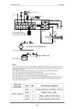
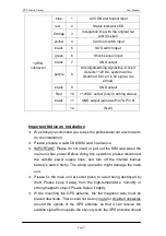
blue
1
ACC ON alert signal input
red
2
Status indicator LED
Orange
3
Integration line with the original car
alarm
’
s siren
yellow
4
Car door switch input
black
5
SOS switch input
green
6
Shock sensor input
black
7
GND output
purple
8
Arming/disarming signal line. Once it
d12VDC, system will be
disarmed. Once it is 0V signal, it is
armed.
black
9
GND output
Red
10
+12VDC output (only in arming status)
black
11
GND output (same as Pin7 & Pin 9)
12-PIN
connector
12
(Null)
Important Notice on Installation
²
We strongly recommend you to ask the professional car electrician to
do the installation.
²
Please prepare a valid GSM SIM card in advance.
²
IMPORTANT:
Please do not insert or pull out the SIM card when the
main unit has power. Before doing this operation, please disconnect
the outside power supply lines, and turn off the internal backup
battery
’
s switch firstly. The wrong operation might damage the main
unit.
²
Please fix the main unit at secret place to avoid being destroyed by
theft. Please keep it away from the high-temperature, humidity or
strong magnetic object. Please fasten it tightly.
²
While mounting the GPS antenna, the flat magnetic side must be
placed downside. There could not be any metal or shielded obstacles
around the upside of the GPS antenna, so that it can receive the
satellite signal from upside the sky very well, the GPS antenna should


