


DCN: 141-00940-02 7/14/03
4
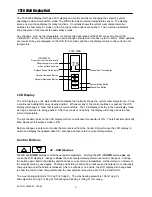
Setpoint Display
The displayed setpoint shows the setpoint of the
current operating mode
(heating or cooling) of the
system. If you change modes, the setpoint displayed will change to the new operating mode setpoint.
If you set the mode to AUTO mode, the setpoint displayed will be the current operating mode of the system,
either heating or cooling. This will change if the operating mode changes automatically.
MODE
The
MODE
button controls the HVAC system mode. To see what mode the system is in, push the
MODE
button
once
and the LCD display will change to
show
the current mode (but won’t change it). Pushing the
MODE
button again while the mode is being displayed, will cause the mode and display to change to the
next mode. The system mode cycles from
Off
to
Heat
to
Cool
to
Auto (
and to
EH
or emergency heat for
Heat Pump systems) and back to
Off
again with each push of the
MODE
button. Any change in the system
mode will be sent to the HVAC Control Unit.
When Heat Pump HVAC system type is selected on the Control Unit, an additional system mode of “
EH”
, or
Emergency Heat, is included in the TS16 mode selections. EH is used when Heat Pump compressor failure
requires the use of Auxiliary Heat (heat strips) for primary heating. When EH mode is selected, the display
will alternate between current temperature and “EH” to remind you that the EH mode has been selected.
FAN
The
FAN
button controls the HVAC system’s manual fan mode. Pushing the
FAN
button once will turn the
fan
ON
and pushing it again will turn the fan to the
AUTO
mode (which is OFF unless the fan is automatically
turned ON by the heating or cooling operation ). The decimal point in the middle of the two digits on the LCD
display will come on when the manual fan is ON. Changes in the fan mode will be sent to the HVAC Control
Unit.
The Control Buttons can be used for other functions and in combinations.
•
Press and hold the UP/DOWN buttons simultaneously to view the Outside temperature. (If an
outdoor sensor is attached or network outside temperature data is available).
•
Press the MODE button and simultaneously press the FAN button to enter the Setup Mode.
•
Buttons are used for navigation in other modes.
Temperature Display
The WDU will normally display the current indoor temperature from the internal digital temperature sensor or
a remote sensor with address 1. The sensors have an accuracy of +/- 1
°
F(+/- .5
°
C) and the range of -67
°
F(-
55
°
C) to 257
°
F(125
°
C).
The WDU will display temperatures from -9
°
F/C to 127
°
F/C. Temperatures less than 0
°
will be displayed
down to -9
°
(temperatures lower than –9 will also be displayed, but without the – sign). Temperatures over
100
°
will be displayed without the leading 1 (ex: 102 will be displayed as 02
°
)
Outside Temperature Display
MODE Button
FAN Button


