RCS txb16 Скачать руководство пользователя страница 2

DCN: 141-00940-02  7/14/03  

2


DO NOT USE THIS PRODUCT FOR BUILDING FREEZE PROTECTION!  YOU ARE ADVISED TO 

INSTALL A MECHANICAL FREEZE PROTECTION DEVICE FOR THIS PURPOSE. 


 TXB16 Operation 


The TXB16 thermostat provides the latest technology in a full-featured universal thermostat with X10 
communications. The TXB16 has many new features including: 
 

• 

Separate Heating and Cooling Setpoints 

• 

Multistage HVAC Systems Support 

• 

Setup Mode from the Wall Display Unit 

• 

Automatic Remote Sensor Detection 

• 

Selectable X10 Decode Table 

• 

Bi-directional X10 Standard 

• 

Enhanced X10 Protocol 

 
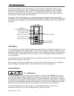
The TXB16 thermostat consists of two parts, a 

TS16


Wall Display Unit (WDU)

 and a 

HVAC


Control Unit

.  

The Wall Display Unit provides users functions like a traditional thermostat and connects to the Control Unit 
by a 4 wire cable.  The Control Unit connects at the HVAC system using the standard thermostat 
connections and provides the thermostatic temperature control of the system.  The Control Unit also has the 
X10 Power Line Interface connection. 
 
The TXB16 now maintains separate heating and cooling setpoints.  The display shows the setpoint of the 
current operating mode (in Auto mode, the system keeps track of the current operating mode of the last call, 
either heating or cooling).  New X10 bi-directional commands have been added for a heating setpoint and a 
cooling setpoint.  Note that the TXB16 maintains compatibility with single setpoint protocols by continuing to 
support the current SP command for both inbound commands and status reports. 
 
In addition to the universal Standard or Heat Pump systems support, the TXB16 supports multistage 
heating/cooling system outputs.  The control unit can support 2 stages of heating and cooling for Standard 
systems, or 3 stages of heating and 2 stages of cooling for Heat Pump systems. 
 
The TXB16 has a convenient setup mode from the Wall Display Unit.  You can set the network address, F or 
C mode and easily calibrate the internal and remote sensors. 
 
The TXB16 has automatic detection and setup of remote temperature sensors.  Remotes sensors have 3 
address settings that, when detected by the TXB16, will be used for specific functions such as in lieu of the 
internal sensor, averaging with other sensors or an outdoor sensor. 
 
The default X10 unit code decode table, B or P can be set to allow compatibility with existing TX15/TX15B 
thermostats and control software.  Changes in decode table selection by using “All lights On” or “All Units 
Off” commands or Preset Dim Commands are now stored in EE prom for permanent selection even with 
power cycling. 
 
 For easy configuration as a replacement for older TX15 thermostats with the “B” decode table, dipswitch 
SW1 position 4 can be set to ON to force “B” decode table use. 
 

The Bi-directional protocol is now included as standard for the TXB16. 

 
Remote control of the TXB16 via the X10 communications protocol allows for the thermostat’s temperature, 
heating and cooling setpoints, operating mode and fan functions to be monitored or changed.   
 
A robust X10 Bi-directional protocol allows full control of all the thermostat setup and operating parameters.   
 
Many new commands have been added to support the TXB16’s new features.  Refer to the X10 protocol 
document, DCN 150-00200.  

Содержание txb16

Страница 1: ...D OPERATION MANUAL DCN 141 00940 Rev 02 7 14 03 Applies to the following revisions or later Product Part No TXB16 Thermostat Kit 001 00940 03 TS16 Wall Display Unit 001 00910 04 HCFX HVAC Control Unit...

Страница 2: ...ports In addition to the universal Standard or Heat Pump systems support the TXB16 supports multistage heating cooling system outputs The control unit can support 2 stages of heating and cooling for S...

Страница 3: ...back to show current temperature The right decimal point on the LCD display will turn on whenever manual fan is ON The left decimal point will flash whenever the setback mode is ON Remote changes in...

Страница 4: ...isplay will alternate between current temperature and EH to remind you that the EH mode has been selected FAN The FAN button controls the HVAC system s manual fan mode Pushing the FAN button once will...

Страница 5: ...onding to X10 house codes A to P Default set to 1 Setting the Fahrenheit or Celsius mode In the setup mode press the mode button to select FC mode Press the UP DOWN buttons to select F or C mode desir...

Страница 6: ...ddress 4 This remote sensor is used for an outside temperature sensor C4 in the calibration setup Table of Remote Sensor Functions and Sensor Addresses Function Remote Addr 1 Remote Addr 2 Remote Addr...

Страница 7: ...sensor is not responding it will display SF In most cases this will clear itself when communications is restored to the sensor A continuous SF display may indicate a problem with the wiring or the WD...

Страница 8: ...Selectable Changeover with Heat or Cool Radiant 2 2 Hydronic 2 2 Pump output STANDARD GAS ELECTRIC HVAC SYSTEMS OPERATION The TXB16 has Standard HVAC system operating modes of Heating Cooling and Aut...

Страница 9: ...check your HVAC system s requirements Note Dipswitch SW1 position 3 the CO selection is not required for standard systems Leave in the Off position SW1 3 OFF TXB16 Control Unit HVAC System Outputs fo...

Страница 10: ...delay period If another call occurs before the delay period expires the CO relay will already be on and this avoids continuously cycling the CO valve on off for each call TXB16 Control Unit HVAC Syst...

Страница 11: ...A to P The X10 address is set from the Wall Display Unit in the Setup mode X10 House Code Address Setting The TXB16 House Code address A to P is set from the Wall Display Unit by entering the setup mo...

Страница 12: ...ways 1 For quick and easy setting the TXB16 to be compatibility with older TX15 software that used the B Decode Table set the control unit dipswitch SW1 position 4 ON In this position the decode table...

Страница 13: ...a thermostat wiring 4 Wires TXB16 Control Unit Heating Cooling System TXB16 Wall Display Unit Thermostat Replace Thermostat with Wall Display Unit Insert Control Unit into the thermostat wiring 4 5 or...

Страница 14: ...a two twisted pair cable 24 Ga minimum Cat 3 or 5 4 pair cabling is acceptable In retrofit applications the existing thermostat wiring a least 4 wires may be adequate However such non twisted wiring...

Страница 15: ...1 00940 02 7 14 03 15 The TS16 WDU has an addition connector J2 on the WDU base for connection of an external remote temperature sensor Follow the wiring diagram with the remote sensor to connect to t...

Страница 16: ...ed to refer to your HVAC system s documentation for specific information on its thermostat connections and setup requirements You must know the following 1 HVAC system type Gas Electric Heat Pump Radi...

Страница 17: ...R 24VAC Return C 24VAC Common Red Green White Yellow RH W1 Heat 1 G Fan Y1 Comp 1 W2 Heat 2 HVAC SYSTEM THERMOSTAT CONNECTION TXB16 Control Unit Typical thermostat wiring color codes Y2 Comp Stage 2...

Страница 18: ...HVAC System G Fan W1 Heat Stage 1 Y1 Comp Stage 1 R 24VAC Return C 24VAC Common Red Green White Yellow RH W1 Heat 1 G Fan Y1 Comp 1 O CO HVAC SYSTEM THERMOSTAT CONNECTION TXB16 Control Unit Typical th...

Страница 19: ...problems or in doubt about the cable check the cable with the simple inspection shown below Power Connection The TXB16 Control Unit requires 12VDC 200ma max Connect the provide transformer to jack J4...

Страница 20: ...n t make sure the Status LED is not flashing twice indicating minimum off delay wait until LED stops flashing twice before proceeding 11 Press the Mode button until the WDU is showing O for OFF The He...

Страница 21: ...ded that you install the TXB16 and Control Unit and then rerun these quick tests BEFORE you connect the controller to the HVAC system You will be confident that the TXB16 is working correctly before y...

Страница 22: ...e following terminals Function Test HVAC Terminals Result Fan R to G Fan should come on Heating R to W Heat cycle should start for heating Cooling R to Y and G Compressor and Fan should start for cool...

Страница 23: ...ometimes referred to as reversing valve output to switch between heating and cooling Most Heat Pump systems are change over with cooling and SW1 3 should be set to CO COOL OFF position Check your HVAC...

Страница 24: ...DCN 141 00940 02 7 14 03 24 Note The default SW1 switch setting is all OFF Standard System No Fan Heat CO Cool P decode table...

Отзывы: