- 3 -
INSTALLATION OPTIONS.
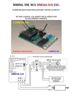
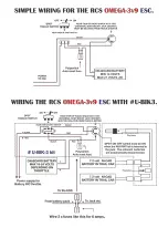
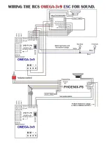
There are a number of different ways to wire up a loco. See wiring diagram pages. The two most popular are:
1. The simplest method is to connect the motor outputs (M & M) to what were the now isolated track pick ups. The loco
will behave exactly as it would if it were running on track power. That is, the lights for example will rise and fall with motor
voltage or come on before the loco starts moving. No other changes are necessary. This is ideal for trail car set ups.
2. Rewire the lights so that the loco will have constant brightness auto reversing head and tail lights. This can get
complicated and is not advised unless the installer has some experience. See below.
POWER SOURCES.
The
#
OMEGA-3v9s
ESC can only be used with battery power as it comes. Ensure the battery pack is fully charged
before use. Contact RCS for information on how to use the ESC with a constant track voltage.
N.B. The absolute minimum voltage is 14 volts. If you use any less voltage the system will still respond, as in
the LED’s will light and respond to direction change, but the motor drive output will not work.
Connect the traction battery, which
MUST BE FUSED,
as per the wiring diagram.
RCS
R/C
offers a variety of installation kits for on board use such as the
# BIK-U3/6
which has screw terminals to simplify
installations. For trail car installations we also have the
# BIK-TC2/3
.
MOTOR CONNECTION.
With
#
OMEGA-3v9s
connect the motor(s) as per the wiring diagrams to
M
&
M
. The
M +
motor output is positive (+) in
a forward direction. Our extensive testing has shown the system
doesn’t need any motor “Noise” suppression.
SHORT CIRCUIT & OVERLOAD PROTECTION.
RCS
ESC’s
are self protecting. Although there is output overload and short circuit protection built into them, it is
essential the battery supply be fused for overall system protection. See the wiring diagram pages.
LOCOMOTIVE LIGHTING.
RCS
ESC’s
have transistor controlled directional lighting. Please note: Maximum current is 100 ma per terminal.
N.B. Any greater load than 200 ma will kill the switching transistors which are not covered by warranty.
2
– 3 LED’s per output will be just fine but, please do not try and run multiple incandescent bulbs with the outputs. .
The
#
OMEGA-3v9s
requires connecting the lights to the 4 x screw terminals as per the ESC diagram.
+
= Common
+
voltage (input less .7 volt).
-
= Common
–
(ground),
F
= Front Light,
R
= Rear Light.
IT IS MOST IMPORTANT THAT THE LIGHT BULBS BE COMPLETELY ISOLATED FROM ANY OTHER WIRING.
Instead of rewiring some locos, sometimes it is much simpler to control the regular loco wiring by simply reversing the
traction battery voltage. You can use the
# RELAY-1v3
to do this as it can save a lot of wiring in many locos. It is
especially useful in USA Trains
®
locos to control incandescent bulbs or LED’s up to 1 amp & smoke features.
Please note: If the
# RELAY-1v3
is used, the lights will flash alternately, not together as with transistor outputs.
When the system is in neutral only one set of lights will be lit.
The instructions assume the operator has used the available front & rear transistor lighting outputs or
# RELAY-1v3.
If you do not have any lighting outputs connected you MUST be able to observe the LED
’s on the ESC.
DEFAULT START UP DIRECTION.
In case the system is wired back to front, the default direction will also need to be reset. See page # 6 section
3.4
. You may also need to reverse the
F
&
R
lighting wires.
THE PICS BELOW SHOW:
1. Using servos with
#
OMEGA-3v9k
.
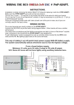
2. Plug in Rx-
ADAPT allows remote placement of Rx. Ideal for Rx’s with end mount servo pins.

