


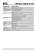


ESC-006 A
5
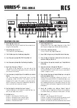
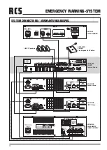
PANNELLO POSTERIORE ESC-006 A
1. Linea altoparlanti 1-6
Prego notare che il cavo degli altoparlanti in linea 100V
deve essere collegato proveniente dall’amplificatore.
2. Uscita linee dell’altoparlante
1-6 un’uscita di 100V dagli altoparlanti.
3. Linea 100V di ingresso dell amplificatore di backup
4. Linea di bassa frequenza (output) di uscita del cavo
audio in 100V per zona 1-6.
5. Linea di bassa frequenza (output) per l’amplificatore
di backup
6. Ingresso per bassa frequenza “Musica”
Questo segnale può essere regolato e controllato sul
frontale del VARES. Per attivare la musica o controllare il
volume, spingere il tasto.
7. Linea a bassa frequenza (output) input per un segnale
esterno supplementare
Questo input ha la priorità sull’ingresso “musica” e la
stazione microfonica VLM-105. Il contatto (8) deve esse-
re ponticellato per attivare questo segnale. Il volume può
essre regolato dall’esterno. Il segnale è trasmesso a tutte
le zone installate ed il volume è regolato tramite il modulo
di playback.
8. Input del contatto per attivare l’input “extern”
La linea di bassa frequenza è attivata via un potenzia-
le contatto libero, per esempio un’interruttore a tempo.
9. DIP switch 1 - 4
Switch 1 = pre chime per VLM-105 on/off
Switch 2 = inserimento / disinserimento impedenza on/off
Switch 3 = tolleranza d’impedenza del 10% o 20%
Switch 4 = inserimento / disinserimento della messa a terra
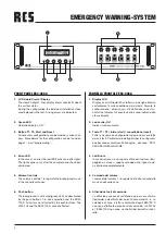
REAR PANEL ESC-006 A
1. Input Speaker Lines 1-6
Please note that the 100V cable must be connected co-
ming from the amplifier.
2. Output Speaker Lines 1-6
100 V output to the loudspeakers
3. 100 V Cable input for the Backup Amplifier
4. Low Frequency (output)for 100 V Amplifier 1-6
5. Low Frequency (output)for the Backup Amplifier
6. Input Low Frequency “Music”
This signal can be adjusted on the front side of the
VARES. To activate the background music or control the
volume, push the button.
7. Low Frequency (output) Input for additional external
Signal
This input has priority over the input “music” and the
microphone station VLM-105. The contact has to be
bridged for this signal. The volume can be adjusted ex-
ternal. The signal is sent to all installed zones and the vo-
lume is adjusted via a playback module.
8. Contact Input to activate the Input “extern”
The low frequency is activated via a potential free con-
tact, for example a time switch.
9. DIP Switch 1-4
Switch 1 = Pre chime for VLM-105 on/off
Switch 2 = Impedance measurement on/off
Switch 3 = Impedance tolerance 10 or 20 %
Switch 4 = Ground fault on/off