


9
EN
4. RIGGING THE SYSTEM
RCF SHAPE DESIGNER SOFTWARE AND SAFETY FACTOR
The suspension system is designed to have a proper safety factor (configuration dependent)� Using the “RCF Easy Shape Designer”
software it is very easy to understand safety factors and limits for each specific configuration� To better comprehend in which safety
range the mechanics are working a simple introduction is needed: HL 6 arrays’ mechanics are built with certified UNI EN 10025 Steel�
RCF prediction software calculates forces on every single stressed part of the assembly and shows the minimum safety factor for every
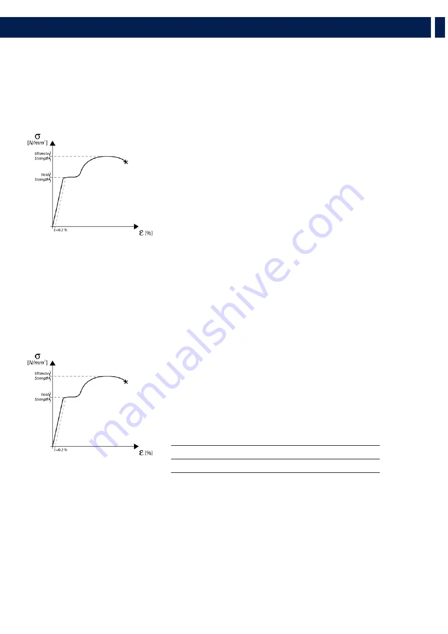
link� Structural steel has a stress-strain (or equivalent Force-Deformation) curve as in the following:
The curve is characterized by two critical points: the
Break Point
and the
Yield
Point
� The tensile ultimate stress is simply the maximum stress attained� Ultimate
tensile stress is commonly used as a criterion of the strength of the material for
structural design, but it should be recognized that other strength properties may often
be more important� One of these is certainly the Yield Strength� Stress-strain diagram
of structural steel exhibit a sharp break at a stress below the ultimate strength� At this
critical stress, the material elongates considerably with no apparent change in stress�
The stress at which this occurs is referred to as the Yield Point� Permanent deformation
may be detrimental, and the industry adopted 0�2% plastic strain as an arbitrary limit
that is considered acceptable by all regulatory agencies� For tension and compression,
the corresponding stress at this offset strain is defined as the yield�
In our prediction software the
Safety Factors
are calculated considering the
Maximum Stress Limit
equal to the
Yield Strength
,
according with many international standards and rules�
The resulting Safety Factor is the minimum of all the calculated safety factors, for each link or pin�
This is where you are working with
a SF=7
Depending on local safety regulations and on the situation, the required safety
factor can vary� It is responsibility of the owner or rigger to make sure that
the system is properly rigged in accordance with Country and local laws and
regulations�
The “RCF Shape Designer” software gives detailed information of the safety factor
for each specific configuration�
The results are classified in four classes:
GREEN
SAFETY FACTOR
> 7
SUGGESTED
YELLOW
4 >
SAFETY FACTOR
> 7
ORANGE 1�5 > SAFETY FACTOR
> 4
RED
SAFETY FACTOR
> 1�5 NEVER ADMITTED
Содержание 1736984
Страница 1: ...HL 6 LINE ARRAY MODULE HL 35 FLYABLE SUBWOOFER OWNER S MANUAL MANUALE UTENTE ...
Страница 2: ......
Страница 13: ...13 EN 4 RIGGING THE SYSTEM ...
Страница 37: ...37 IT 4 APPENDIMENTO DEL SISTEMA ...
Страница 52: ...52 HL 6 DIMENSIONS ...
Страница 53: ...53 HL 35 S DIMENSIONS ...
Страница 55: ...55 EN ...


