background image

RC-Xplanes EDGE 540 T Outrunner Tabs Instruction Manual 

Page 6 of 10                         

Distributed by RC-Xplanes 541-261-2707 

rcxplanes.com


A

2005


4C: 

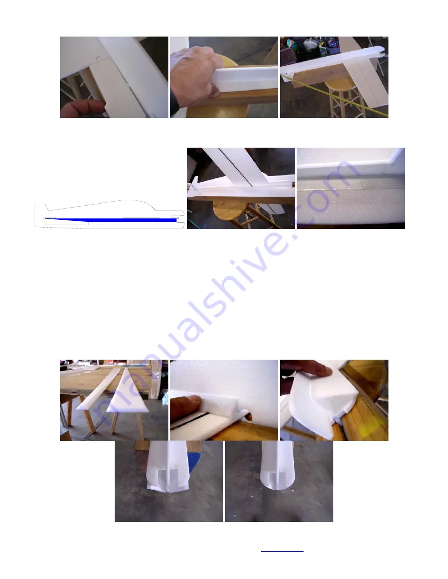
In the area indicated in shade, Install 3/4” strapping tape on both sides of the fuselage. Trim it as shown for a taper from 10” to zero at the 
stabilizer trailing edge. Use a heat gun or hair drier on low or a covering iron with a cover sock to adhere the tape to the fuse. Do not 
overheat the foam. It is more resistant to heat than most foam but can be melted.


10"


Step 5: 45 Degree Support System 

5A: 

Find the two long 45 Degree Fuselage Supports that run from the rear stabilizer trailing edge to the motor mount area and prepare them 
with a 45 degree bevel for the entire thickness of the foam and length of the part on both long edges facing the same surface. You should 
have two parts that are prepared like the left picture below. 
 Start by lining up the narrow end of the 45 Degree Support with the stabilizer trailing edge. Use thin, foam safe RC-Xplanes CA to tack 
glue about 1" of the support at the rear aligned with the stabilizer trailing edge, 1” at the wing trailing edge and 1” at the front end on the 
fuselage and 90 degree supports. When you are satisfied with the alignment, apply some accelerator to these six points to hold it in place. 
Now use light pressure to hold the support against the fuselage and 90 degree supports. Run a bead of the RC-Xplanes thin CA along the 
45 degree support to fuselage joint and the 45 to 90 degree support joint to the wing trailing edge. When you are satisfied with its 
placement, use just enough pressure to hold it in place and not distort the fuselage while you apply the accelerator to the portion of the 
support joints that CA has been applied stopping short of the end of the last CA application by an inch or so. Continue this process to the 
front of the fuselage. Repeat the process for the other side. 
 Trim the overhanging front edge of the 45 degree support even with the profile of the front radius of the front 90 degree fuselage support 
to finish it off. The right picture below shows what the front should look like after you have trimmed it. You should really be able to notice 
the rigidity of the triangulated RC-Xplanes fuselage system as compared to any other foamy you have built. 


Содержание EDGE 540T SMS Tabs

Страница 1: ...RC Xplanes EDGE 540 T Outrunner Tabs Instruction Manual Page 1 of 10 Distributed by RC Xplanes 541 261 2707 rcxplanes com A2005 RC Xplanes EDGE 540T SMS Tabs Instruction Manual...

Страница 2: ...e 6 1 2 length heat shrink 7 1 2 75 x 3 8 square hardwood motor mount 1 small parts bag including 1 15 DuBro Micro hinges 2 4 DuBro Micro control horns 3 4 DuBro Micro E Z links 4 4 DuBro Micro E Z co...

Страница 3: ...and put a small mark at four locations on the spar side of the wing and stabilizer Two at the leading edge and two at the trailing edge for later reference when installing the wing and stabilizer into...

Страница 4: ...es per aileron Mark the rudder on the double beveled edge at 0 5 down from the counter balance 0 75 from the bottom edge of the rudder and half way between these two marks for three hinge center marks...

Страница 5: ...Slide the stabilizer forward engaging the tabs and slots at the leading edge of the stabilizer Insure that the tabs and slots at the wing and stabilizer are even with the front and rear of the 90 degr...

Страница 6: ...ar aligned with the stabilizer trailing edge 1 at the wing trailing edge and 1 at the front end on the fuselage and 90 degree supports When you are satisfied with the alignment apply some accelerator...

Страница 7: ...s for each elevator half and the rudder 6C In this step you will test fit the elevator joiner to the elevators and prepare some waxed paper spacers and tape to hold everything aligned while the adhesi...

Страница 8: ...Make a 1 line extending away from the wing trailing edge at 90 degrees to the line you made at 1 3 8 along the trailing edge This will be your visual reference when installing the servo mounts to the...

Страница 9: ...one at the far right of the left picture below using a pair of diagonal cutters Once modified the control horns will allow for full control surface movement and can be mounted at the locations marked...

Страница 10: ...r each surface without bind and apply your favorite exponential to these Make your low rates 50 of the high rates with your favorite exponential for them For a Hacker A20 22L or AXI 2212 26 set your E...

Отзывы: