28
FUTERA II INSTALLATION AND OPERATION INSTRUCTIONS
3. When fi re tested at the factory the unit’s input was
rated and the gas pressure(s) recorded on the test
label affi xed to the jacket next to the junction box. To
confi rm the input of the unit follow the instructions in
the INPUT RATE section below. The gas pressure
setting(s) for dual fuel units may vary; refer to the test
label on the unit.
4. An undiluted fl ue gas sample must be taken at the
fl ue outlet using a calibrated fl ue gas analyzer. Allow
the unit to run for 15 minutes before taking
the sample. For a natural gas unit the low fi re CO
2
reading should be 7.3%-7.5% and 8.5%-8.8%
for propane gas. The high fi re CO
2
reading should be
7.5%-8.0% and 8.8%-9.4% for propane gas.
Exceeding 8.0% on natural gas or 9.4% on propane
gas CO
2
will shorten the life of the burner. Adjust the
inlet air damper to achieve the correct CO
2
readings.
5. If the pressure settings vary from those listed in Table
8, please affi x a new label or notice to the boiler, which
shows these new settings. However, do not sacrifi ce
or compromise safe combustion, carbon monoxide
limits, or safety settings to achieve these fi gures. The
pressures listed in Table 8 are guidelines obtainable
under ideal conditions.
6. To test the ignition safety shutoff device, close the
manual shutoff valve in the gas supply line. Within 5
seconds of main burner fl ame extinction, the main gas
valve solenoid should close with an audible noise. After
15 seconds the module should lockout and the trial for
ignition end. After 5 minutes a second trial for ignition
should occur. Open the manual shutoff valve in the gas
supply line and reset the ignition control system. A
normal ignition sequence should take place. If the
burner hasn’t lit after the last ignition try, the gas valve
will close and the system will go into lock out only on
CSD-1 units otherwise, the boiler will retry every 5
minutes. Inspect the ignition system to determine what
the problem is.
7. With the main burner in operation, close the manual
fi ring valve. As soon as the main burner fl ames go out,
open the manual firing valve. A normal ignition
sequence should take place. If the burner fails to light
the system will make one more ignition attempt.
8. With the burners in operation, interrupt the power to
the control circuit by lowering the operating control or
thermostat. The main burners should go out. Reset the
operating control or thermostat, a normal ignition
sequence should follow.
Air Box Pressure
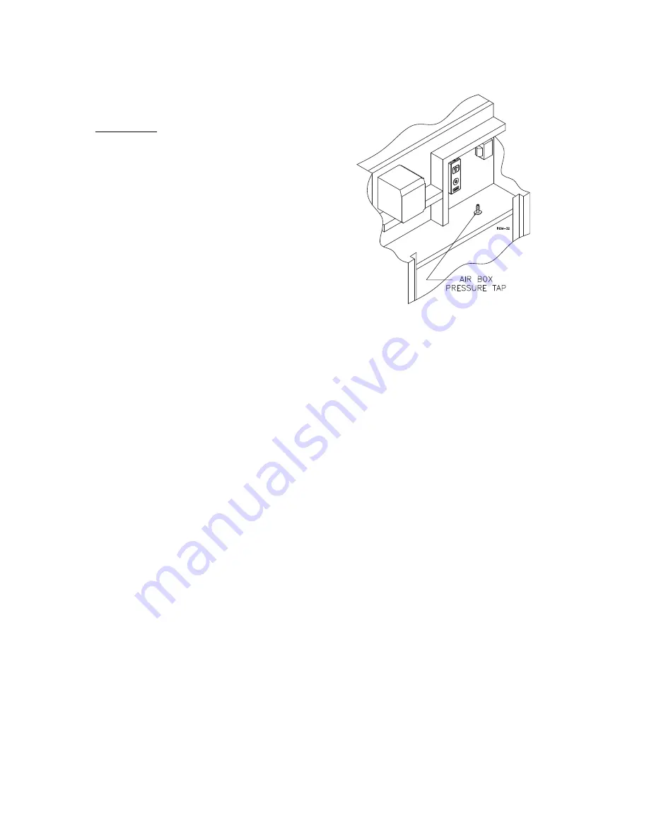
Connect a manometer to the air box pressure tap located
behind the control cover, Figure 21.
Table 9 lists the factory settings for the air box pressure
and gas back pressure that were set using a minimum
length of vent pipe. It may be necessary to adjust the air
shutter on the blower to achieve acceptable combustion
readings for certain installations.
Figure 21 – Air Box Pressure Tap
If vented vertically ensure that the barometric damper is
capable of maintaining the air box pressure listed in Table
9. An air box pressure lower that that listed in Table 9 can
signifi cantly reduce the life of the burner.
Long horizontal vents will result in an air box pressure
higher that that listed in Table 9. It may be necessary to
open the air damper to obtain the correct combustion
settings.
Required Gas Pressure
Connect a manometer to the gas pressure test port
upstream of the fi ring valve, Figure 22. Close the manual
shut off valve for the pilot gas. Ensure that the fi ring valve
is in the open position. Energize the unit and allow it to try
for ignition until it goes into fl ame failure. If the gas back
pressure is signifi cantly different from that listed in Table 9
the air/gas mixing tube may be misaligned.
Provide gas supply pressure at inlet to boiler gas train as
follows:
LP
Nat
Minimum (in W.C.)
11
5
Maximum (in W.C.)
14
14
Measure pressure when the boiler is fi ring at full rate. Low
gas pressure could indicate undersized gas line or
insuffi cient gas supply.


