


Building Instructions JIMMY
Page
van
16
20
Propulsion and controls
Propellor, r.p.m. and battery voltage can be applied in different combinations to achieve
appropriate propulsion. The following combination works well on the prototype:
Battery: 3s lipo type, 1000mAh, which stands for 3 cells in series (= nominal voltage
11.1V) with a capacity of 1000 milliAmpere/hour
Motor: outrunner 100W type, 1100KV (1100KV = 1100 r.p.m. per Volt)
Propellor: 7 x 4 ( = 7 inch diameter, 4 inch pitch)
What remains is to choose a motor controller a.k.a. ESC (= Electronic Speed Controller).
Although current draw of the combination as described above will be around 10A
maximum, it makes sense to choose an ESC suitable for a maximum continuous current
of 20-25A. A BEC (= Battery Elimination Circuit) supplies power to the receiver and
servos) is integral with most ESCs, if not it will have to be added separately.
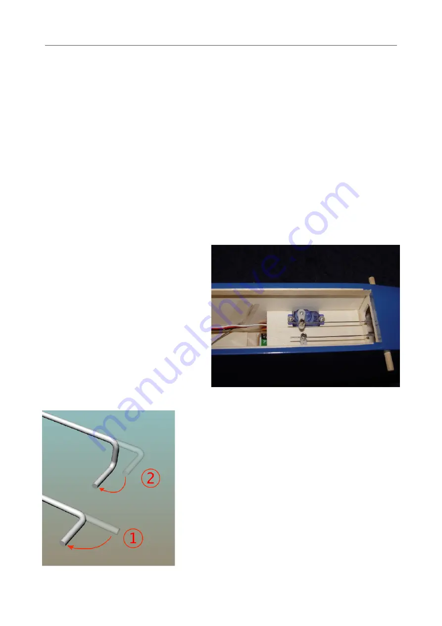
The rudder and elevator pushrods are
connected to the servo arms with
cylindrical connectors into which the
pushrod is clamped with a setscrew.
Drill the hole in the arm which is
approx. 10 mm from the servo center to
the correct diameter (usually 1 or 2
mm) to receive the connector, which
should be free to rotate with a minimum
of play. Mount the connectors on the
arms and mount the servos in the
dedicated openings.
Cut the two pushrods from a length of 0.8 mm dia.
pianowire. Bend the ends in two steps as shown in
the picture, leaving approx. 2 mm straight where it
rotates in the control horn. Slide the pushrods into
the control cables in the fuselage from behind,
pass them through the servo connectors and twist
the bent end into the hole of the control horn, see
the pictures on the previous page.
Make sure the servo is in its neutral position with
the arm at 90 degrees, and fasten the setscrews of
the connectors
Содержание JIMMY
Страница 20: ...Building Instructions JIMMY Page van 20 20 ...


