background image


V1.0 


RayToos AG. © Copy Right 


www.raytools.ch


BM110 SERIES (Chinese Model) 3.3KW Auto Focus Laser Cutting Head

-

User Manual


18  | 20


5.3.2


Replace Nozzle


Screw the nozzle.


Replace the new nozzle and re

-

tighten it properly.


Once the nozzle or ceramic structure has to be replaced, capacitance calibration must be 

done again.


6


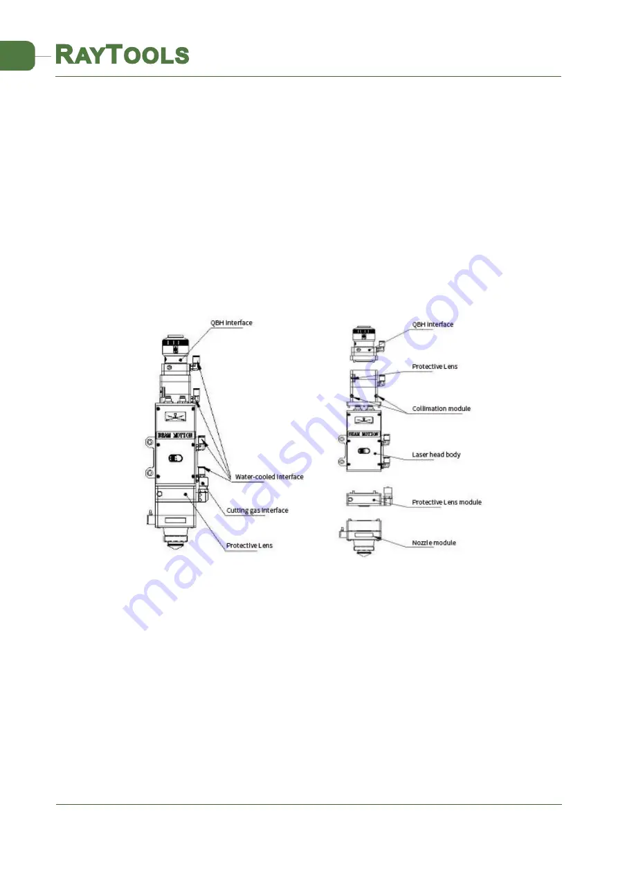
Mechanical and Optical Configuration


6.1


Physical Structure


Содержание BM110 Series

Страница 1: ...BM110 SERIES Chinese Model 3 3KW Auto Focusing Laser Cutting Head User Manual Email sales raytools com Add Friedeggstrasse 13 Postfach 3400 Burgdorf Switzerland...

Страница 2: ...l makes a detail introduction about the use of BM110 series auto focusing laser cutting heads including installation operation and maintenance instructions etc If you have other things need to know pl...

Страница 3: ...and Commissioning 9 3 1 FSCUT BC with position mode 9 3 1 1 Wiring 9 3 1 2 Interface Operation 10 4 Adjustment of Beam Center and Focus Position 11 4 1 Beam Center Position Adjustment QBH interface 1...

Страница 4: ...ed by RAYTOOLS in 2020 The products are equipped with internal servo motor drive units which use the linear mechanism to drive the focusing lens to change position in the range of about 22mm automatic...

Страница 5: ...dent laser into a parallel beam and adjust the beam spot from the center of the nozzle Focusing driver module The collimating beam is focused into a small beam spot which has high power density and th...

Страница 6: ...arranged arbitrarily It is important to note that when the laser power is greater than 500W we recommend users to use water cooled As you can see from Figure 2 2 the position and quantity of the water...

Страница 7: ...The higher the purity of the gas the better the quality of the cutting section Impurities can be filtered out in gas supply tube but Oxygen and water vapor can permeate light path through non metalli...

Страница 8: ...ing head with motor power cable encoder cable sensor cable respectively as shown in figure 2 3 After the proper length is reserved the cable is inserted into the track groove of the machine tool and f...

Страница 9: ...fiber is vertically inserted in the laser head the laser head must be rotated 90 degrees to the horizontal level and then inserted the optical fiber in it to prevent dust from entering the interface...

Страница 10: ...erfaces of motor and shall be wired as below White Red Pink Blue 24V 0V Up limit Low limit Note The limit sensor is NPN NC and it continuously outputs 0V signal when it is not triggered Open the platf...

Страница 11: ...moving the J axis so that it meets the positive and negative limit check whether the direction and limit signal are normal or not 3 By click homing icon J axis moves to negative direction and do 2nd...

Страница 12: ...decreased Beam center position adjustment of the laser cutting head can be finished by adjusting Collimating lens X Y direction The adjusting screws are located on the top of the cutting head as shown...

Страница 13: ...ser power range is set to 80 100w 2 Then within each moving 0 5mm as small as possible activate the laser to make a hole in the textured paper 3 Dotting several times finally compare and find out the...

Страница 14: ...e to wipe back and forth to avoid secondary lens pollution and use rubber gas blowing to sway the surface of the lens Both sides should be cleaned After cleaning make sure that there are no residues d...

Страница 15: ...Removal and Installation of Top Protective Lens Unscrew the locking screw of the top protective lens assembly with a 3mm Allen wrench Remove the top protection lens cover and hold both sides of the dr...

Страница 16: ...ting lens mount and remove the spring pressure ring and the collimating lens with the lens removing tool Clean or replace the collimating lens As shown below reassemble the collimating lens components...

Страница 17: ...ring and focusing lens with a lens removing tool Replace or clean the focusing lens As the direction shown below put the focusing lens and the spring pressure ring in the lens mount carefully and tigh...

Страница 18: ...need to replace the nozzle connector if it gets damaged 5 3 1 Replace Ceramic Structure Unscrew the nozzle Hand pressing the ceramic structure so that it is not skewed and then unscrew the pressure s...

Страница 19: ...Laser Cutting Head User Manual 18 20 5 3 2 Replace Nozzle Screw the nozzle Replace the new nozzle and re tighten it properly Once the nozzle or ceramic structure has to be replaced capacitance calibr...

Страница 20: ...V1 0 RayToos AG Copy Right www raytools ch BM110 SERIES Chinese Model 3 3KW Auto Focus Laser Cutting Head User Manual 19 20 6 2 Optical Configuration 6 2 1 Collimation Length 6 2 2 Focus Length...

Страница 21: ...V1 0 RayToos AG Copy Right www raytools ch BM110 SERIES Chinese Model 3 3KW Auto Focus Laser Cutting Head User Manual 20 20...

Отзывы: