‘3.2.2
Display
A
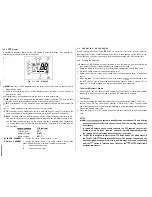
of indicators appear on the LCD display in different locations. The following list
describes each indicator and when it will appear.
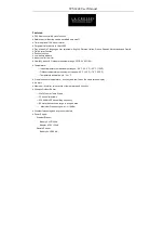
Fig. 3-2 LCD DISPLAY
MEM
(Memory) : will be displayed when the current channel is a memory channel, and in
Memory Scan mode.
SCAN (All Scan/Memory Scan) : will be displayed when the radio is In the All Scan or
Memory Scan mode.
MON (Monitor) : will be displayed when the radio is in the Monitor mode.
WX
(Weather) : will be displayed when a weather channel is selected. The “WX” indicator
will blink when a severe weather alert tone is received (in Monitor mode).
INT
(International) : will be displayed when International channels are programmed for
use.
5 1 : will be displayed to indicate the current TX power setting.
TX
(Transmit) : will be displayed on the LCD when the Push-To-Talk (PTT) switch on the
radio is engaged and the transmitter circuits are providing RF signals to the antenna.
is always shown on the display along with the battery voltage bar indicators to pro-
vide a battery level status. The
indicator will blink when the battery voltage is low,
and the battery needs charging. If a low battery condition is detected during transmission,
“LO” will be shown and the radio will stop transmitting. The battery level is shown on the
LCD as follows:
LCD Indicator
Fully charged
Normal operation
BATT --
Needs charging
BAT-T --
@ LARGE CHANNEL
: displays the channel number currently in use.
SMALL CHANNEL
: displays the channel number of the priority channel in Monitor mode.
Other indicators shown in the Small Channel segment area:
C :
indicates Canada mode.
P :
indicates Priority mode.
3 . 3 O P E R A T I N G P R O C E D U R E S
Specific operating procedures for the
RAY100
are presented in this section. General information
regarding correct marine channel usage may be found in the Appendix section. Refer to the
Control section 3.2.1 beginning on page 9 for a thorough description of all RAY100 functions.
3.3.1
Turning the Power On
1)
Rotate
the ON/OFF/Volume control clockwise to turn the radio on. Continue rotating the
knob clockwise and set it at approximately the midpoint of it’s range.
2) Rotate the SQUELCH control fully counterclockwise. (Background noise will be heard.)
3 ) Set the VOLUME control to the desired listening level.
4 )
Rotate the SQUELCH control slowly clockwise until the background noise in the speaker
ceases.
5 )
When the power is initially turned on, the priority channel
will be selected. Press
the
channel keys to select the desired working channel. Refer to section 3.3.7 on
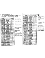
pages 16 16 for the available VHF Marine channels and their frequencies.
To Select A Weather Channel
1 ) Press the WX INT key, then the
channel keys to select your local NOAA weather
channel (0 to 9). When the WX mode is selected, the transmitter is inhibited.
To Transmit
1 ) To select or change the transmitter output power, press and hold the MON
key for 1
second. There are two output power settings: 5 Watts, and Watt. The appropriate
power setting depends on the distance the message is to be transmitted, transmitting con-
ditions, and desired battery life.
2)
Press the Push-To Talk (PTT) switch and speak into the microphone using a clear normal
voice.
N O T E S :
Initial
contacts are usually made over channel 16 as all ships
and shore stations monitor this channel, then a shift to a worklng channel will
be necessary.
In certain US harbors and on certain channels, the FCC requires the
power to be
limited to 1 watt. On these “required” channels, the radio automatically selects
the watt power output setting when the channel is selected.
The RAY100 is designed to meet the new FCC Rules Part 60.203, which states. if
the Push-To Talk
switch is
for over five minutes continuously, the
transmitter
disengage. If this occurs, audible beeps will sound continuously
until the
switch is released. Upon release of the
normal radio
operation
resume.
Содержание Ray 100
Страница 2: ...b Instruction Manual...


