background image

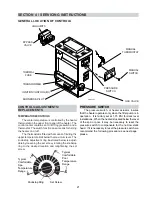
PRESSURE SWITCH ADJUSTMENT:

1. With pump and heater on, turn adjustment

knob (clockwise) until a click is heard from the
gas valve.

2. Turn adjustment knob (counter clockwise) 1/4

turn.

3. Turn pump off and on several times.  Heater

should shut off immediately.  If it does not,
repeat steps above until proper adjustment is
made.

Adjustment Knob

Fig. # 8069.1

Heat Exchanger Height

5' Max.

Heat Exchanger Height

Pool or Spa

Fig. # 8152.0s

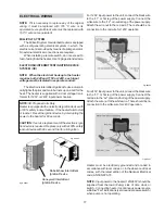
NOTE: 

If heater is installed outside of the limits shown,

a flow switch must be used in place of the pressure
switch when mounted and wired adjacent to the heater.

TWO SPEED PUMPS

In some cases, the flow on the low-speed is insuf-

ficient to operate the heater.  This is apparent when the
pressure switch cannot be further adjusted or if the
heater makes banging noises.  In these cases, the
pump must be run at high speed when heating the
water.

CAUTION:

 Do not operate the heater without the func-

tion of a properly adjusted pressure switch.

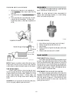
HIGH LIMITS

The heater is equipped with two automatic high

limits.  Both are set to open at 135°F.

NOTE:

  An erratic high limit is often characteristic of

internal heat exchanger problem, i.e. scale buildup.
Refer to troubleshooting section.

Fig. #9275

HIGH LIMIT REMOVAL

1. Shut off main electrical power switch to heater.
2. Remove inspection panel and box cover.
3. Drain heater.
4. Remove defective high limit and replace with a new

high limit.

5. Reverse above procedure to re-installl.

PILOT SAFETY

PILOT SAFETY 

(Millivolt System)

The heaters equipped with the standing pilot (millivolt

system), have pilot generators which act as a safety
device to shut off the flow of gas to the main burners and
the pilot burner in case the pilot flame is extinguished.
The pilot burner must be manually relighted to place the
heater in operation again.  Refer to the lighting instruc-
tions provided on the heater label.

PILOT SAFETY

 (IID Units) ELECTRIC IGNITION

The heater employs a pilot safety which closes the

main gas valve within 8/10ths of a second whenever the
pilot flame is interrupted.  Pilot flame is automatically lit
when the device is powered.  Unit performs its own
safety check and opens the main valve only after the
pilot is proven to be lit.

22

5' Max.

Содержание Versa 105B Brass

Страница 1: ...pliance Do not touch any electrical switch do not use any phone in your building Immediately call your gas supplier from a neighbor s phone Follow the gas supplier s instructions If you cannot reach your gas supplier call the fire department Installation and service must be performed by a qualified installer service agency or the gas supplier Do not store or use gasoline or other flammable vapors ...

Страница 2: ......

Страница 3: ...S 9 CodeRequirements 9 BaseInstallation 10 Clearances 11 CombustionAir 12 VentingConnections 14 Gas Supply Connections 15 Plumbing for Water Connections 17 Electrical Wiring 21 SECTION 4 SERVICING INSTRUCTIONS 21 GeneralLocationofControls 21 Control Adjustments Replacements 21 Pressure Switch 22 High Limit 22 Pilot Safety 23 BurnerDrawerRemoval 23 GasValveRemoval 23 Main Burner Orifice Removal 23 ...

Страница 4: ...als Do not obstruct the flow of combustion and ventilating air 4 WATER Firstthing insurethatsystemisfilledwithwaterand havepumpoperating Watermustbeflowingthroughthe heaterduringoperation Fig 9258 FOR YOUR SAFETY READ BEFORE OPERATING WARNING IF YOU DO NOT FOLLOW THESE INSTRUCTIONS EXACTLY A FIRE OR EXPLOSION MAYRESULT CAUSINGPROPERTYDAMAGE PERSONAL INJURY OR LOSS OF LIFE SECTION 1 START UP PROCED...

Страница 5: ...ined areas extra care should be exercised when lighting propane heaters 8 Turn knob on gas control counter clockwise to Pilot 9 Push in control knob all the way and hold in Immediately place flame to pilot to light Continue to hold control knob in for about 1 minute after the pilot is lighted release knob and it will pop back up Pilot should remain lighted If it goes out repeat steps 5 through 9 I...

Страница 6: ...will settle on the floor WHAT TO DO IF YOU SMELL GAS Do not try to light any appliance Do not touch any electric switch do not use any phone in your building Immediately call your gas supplier from a neighbor s phone Follow the gas supplier s instructions If you cannot reach your gas supplier call the fire department C Use only your hand to push in or turn the gas control knob Never use tools If t...

Страница 7: ...s sure problems should obtain a physician s advice before using pools or hot tubs 6 Persons taking medications which induce drowsiness such as tranquilizers antihista mines or anticoagulants should not use spas or hot tubs SECTION 3 MAINTENANCE AND CARE PROCEDURES To be followed one month after start up and then semi annually 1 Inspect top of heater and draft hood for soot a sticky black substance...

Страница 8: ...ssure Should this occur shut the heater off and contact your gas supplier or qualified service agency 5 On indoor heaters clean room intake openings to assure adequate flow of combustion and ventilation air CAUTION Combustion air must not be contaminated corrosive chemical fumes which can damage the heater 6 Keep area around heater clear and free from combustible materials and other flammable and ...

Страница 9: ... 4 for each 1000 feet above sea level as high elevation reduces combustionperformance SECTION 3 INSTALLATION INSTRUCTIONS IMPORTANTNOTICE These instructions are intended for the use of quali fiedpersonnelonly specificallytrainedandexperienced in the installation of this type of heating equipment and related system components Installation and service personnel may be required by some states to be l...

Страница 10: ...ause water to spray through the cabinet louvers and into the heater This could cause heavy internal rusting or damage some electrical components and this would voidthewarranty Heaters must not be installed under an overhang of less than three 3 feet from the top of the heater Three 3 sidesmustbeopenintheareaundertheoverhang Roofwaterdrainagemustbedivertedawayfromtheheaters installed under overhang...

Страница 11: ...ermust alwaysbeventedtotheoutside SeeVentPipingSection forventingdetails Minimumallowablespaceisshownon thenameplate COMBUSTIONAIR INDOORUNITSONLY Air For combustion And Ventilation Indoor Units Only The heater must have both combustion and venti lation air Minimum requirements for net free air supply openings one 12 inches from ceiling for ventilation and one12inchesfromthefloorforcombustionairas...

Страница 12: ...op to unit VENTTERMINAL Outdoor OUTDOORSTACK STEP 1 Line up 8 holes in jacket top with 8 holes in adapter assembly STEP 2 Lower entire outdoor stack assembly on to jacket top STEP 3 Securewithfastenersprovided 12 VENTTERMINAL Indoor Locate and assemble as shown Secure with screws supplied in envelope inside carton OUTDOORTOP JACKETTOP MOUNTING SCREWS 4 Fig 9255 OUTDOOR STACK W ADAPTER Fig 9256 MOU...

Страница 13: ...s and walls Forprotectionagainstrainorblockagebysnow the ventpipemustterminatewithaventcapwhichcomplies with the local codes or in the absence of such codes to the latest edition of the National Fuel Gas Code ANSI Z 223 1 The discharge opening must be a minimum of two feet vertically from the roof surface and at least two feet higher than any part of the building within ten feet Vent stackshallbea...

Страница 14: ... minimum of 7 W C and a maximum of 14 W C upstream pressure under load and no load conditions must be provided for natural gas or a minimum of 12 W C and a maximum of 14 for propane gas GAS PRESSURE REGULATOR The gas pressure regulator is preset and sealed at 4 W C for natural gas and ll W C for propane gas Between the gas valve and the burners is a l 8 pipe plug The pressure at this point taken w...

Страница 15: ...er tube or 1 1 4 galvanized pipe as a slip connections GASKET DESIGN 2 Loose in a Bag Accepts 2 coppertubeasaslipconnection Theflangeisthreaded for 2 screw in pipe connections Also used with the 2 CPVCadapters 1 2 Fig 8095 1 Fig 8097 1 INLET OUTLETHEADER AUTOMATICCHLORINATORSANDCHEMICAL FEEDERS All chemicals must be introduced and completely diluted into the pool or spa water before being circulat...

Страница 16: ...surerelief valve having a capacity equal to BTU HR output of the modeltobeinstalledisrecommendedforthisappliance A 3 4 NPT connection is provided in the inlet outlet headerforinstallationofapressurereliefvalve Thevalve shall be installed in a vertical position PRESSURE RELIEF VALVE PRV DISCHARGE CONNECTION INLET OUTLETHEADER Fig 8095 0 NOTE To avoid water damage or scalding due to valve operation ...

Страница 17: ...ce by interrupting the power to the heater for 60 seconds CAUTION If service replacement of the electronic igni tiondeviceisrequired Replaceonlywitha100 safety lockout device with 90 second trial for pilot ignition 17 Fig 8929 1 Robertshaw Intermittent Ignition Device Honeywell Intermittent Ignition Device Fig 8085 For 120 V input power to the unit connect the black wire to the L1 or hot leg of th...

Страница 18: ...18 WIRING DIAGRAM MILLIVOLT UNITS Fig 2353 WIRING DIAGRAM KEY Fig 8096 PINK CONNECTOR BLUE CONNECTOR If required by local code install at this location ...

Страница 19: ...WIRING DIAGRAM I I D UNITS IGNITIONDEVICE HONEYWELL Fig 9250 19 ...

Страница 20: ...WIRING DIAGRAM IID UNITS IGNITIONDEVICE ROBERTSHAW Fig 9251 20 ...

Страница 21: ...ng to the desired location and retightening the set screw Typical Comfortable Spa Temperature Range Typical Comfortable Pool Temperature Range Knobstop Ring Set Screw PRESSURE SWITCH The pressure switch or heater actuator insures that the heater operates only when the filter pump is in operation It is factory set at 1 75 PSI for deck level installations When the heater is located below the level o...

Страница 22: ...ipped with two automatic high limits Both are set to open at 135 F NOTE An erratic high limit is often characteristic of internal heat exchanger problem i e scale buildup Refer to troubleshooting section Fig 9275 HIGHLIMITREMOVAL 1 Shut off main electrical power switch to heater 2 Removeinspectionpanelandboxcover 3 Drainheater 4 Remove defective high limit and replace with a new high limit 5 Rever...

Страница 23: ...nlarge hole To remove orifice use a socket wrench and remove from manifold DO NOT overtighten when reinstalling PILOT REMOVAL AND CLEANING 1 Remove burner drawer See burner drawer re moval procedure 2 Disconnect pilot tubing disconnect wires from gas valve 3 Disconnect pilot bracket from burner shield 4 Remove pilot from bracket 5 Remove pilot orifice and air opening Honeywell MV unit only and cle...

Страница 24: ...e sheets Then proceed to collapse studs in the tube sheets with a chisel or screwdriver Use caution not to cut into the tube sheet Replacement tubes will have the fins stripped off longer on one end The long end is inserted into the opening of the tube sheet first then the short end is fitted through the opposite tube sheet If the tube ends become dented or bent straighten at least 4 inches back f...

Страница 25: ...Assembly Fig 8101 0 UNITHERMGOVERNOR U G REPLACEMENT 1 Shut water gas and electricity off close valves and relievepressure 2 Drainheatexchanger 3 Remove retainer plug located under outlet pipe connection 4 Remove spring and replace old U G with a new U G 5 Reverseaboveproceduretore install Gasket U G RetainerPlug Spring Fig 8071 0 TotesttheoperationoftheUnithermGovernor place inhotwater over100 F ...

Страница 26: ...ustment Adjust pressure switch Liming or scale forming on Poolwater See Water Chemistry on page 2 heat exchanger Sooting Highflowrates Reduce by adding manual bypass valve and adjust by putting thermometer in header 1 4 NPT drain opening Set bypass so thermometer reads between 105 and 110 F Airstarvation Refer to installation instructions Improper venting Follow recommended installation instructio...

Страница 27: ...en gas valve knob is released If burner does not remain lit attach millivolt meter and read pilot output If below 500mV check gas pressure Also check for insects or debris in the pilot burner If main burner fires remove jumper Replace gas valve If main burner does not fire remove jumper Remove both TH wires from gas valve Relight pilot If pilot burner stays on Problem is a wire or component short ...

Страница 28: ...t shuts off pilot gas if pilot fails to light To reset interrupt power to heater Intermittent Pilot System TROUBLESHOOTING HONEYWELL S8600 NOTE Before troubleshooting familiarize yourself with the start up and checkout procedure Check line voltage power low voltage transformer limit controller thermostat controller and wiring Pull ignition lead and check spark at module Spark Okay YES Check igniti...

Страница 29: ...t under standard company warranties must be properly tagged with RAYPAK return parts tag completely filled in with the heaterserialnumber modelnumber etc andshippedto the Company Freight Prepaid If determined defective by the Company and within war ranty thepartwillbereturnedinkindorequalsubstitution freight collect Credit will not be issued Manufacturer 2151 Eastman Ave Oxnard CA 93030 29 ...

Страница 30: ...30 ...

Страница 31: ...31 ...

Страница 32: ...32 ...

Отзывы: