DOC-S05
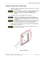
3.5. Mo
508-1R14-IME
ount the C
1.
Mount
the flo
2.
Run ca
3.
Mount
12” fro
EI02 • Technic
Control B
t the Control B
or level. See
If position
need to b
cables ar
problems
ables in spec
Typically
minimum
use ¾” co
or modific
Run cond
drill into t
you are r
t the photo ey
om the floor).
Ensure th
do not pro
cal Manual • I
Box and P
Box on the
m
Figure 2-17.
n of control bo
be purchased
re spliced doo
s.
ific conduit/tra
, the motor ca
m of ½” condu
onduit for the
cations.
duit and/or ca
the side or top
running condu
yes in the pre-
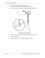
See Figure 3
hat the photo
oject into the
Figu
Issue
Photo Eye
otor side
of t
ox varies from
d. Motor and e
or will be susc
ay dictated pe
able will requ
it for low volta
e low voltage c
ables into the
p of the contr
uit, place the
-drilled holes
3-16.
eyes are flus
side rail.
ure 3-16: Pho
Ch
es
the door, app
m above place
encoder cable
ceptible to int
er NEC or loc
ire ¾” condui
age cables. It
cables instea
bottom of the
rol box. Doing
motor cable i
in the side gu
sh with the ins
oto Eyes
hapter 3: Mec
proximately 5’
ement, additi
e
cannot
be s
termittent or m
cal code.
it and you will
t is our recom
ad of ½” do to
e control box,
g so will void w
in its own con
uides (located
side attachme
chanical instal
23 |
P
3” to center f
onal cables w
spliced. If
major
l need
mmendation to
future add-on
ONLY! Do n
warranty! (If
nduit.)
d approximate
ent nut and
llation
a g e
from
will
o
ns
not
ely


