


Chapter 6: Post Installation Procedures
59
Chapter 6: Post Installation Procedures
Once you have installed the system, you need to confirm that the system
is wired correctly and is also set up to suit your type of boat.
This chapter provides instructions for the following procedures:
• Functional test, consisting of a few simple tests to confirm that the
system is wired correctly
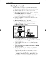
• Dockside procedure, necessary if a rudder reference transducer is
fitted, to ensure that the rudder reference transducer is correctly
aligned with the rudder.
• Initial sea trial, to swing the compass and align the heading, check
the autopilot’s operation and check the rudder gain
Further customisation can be performed after the sea trial, as described
in Chapter 4.
6.1 Functional test
Switch on
Having installed your ST5000 Plus autopilot, switch on the main power
breaker. If the control head is active and the system operating, the
following will occur:
• The control head beeps and displays the pilot type (
5000 SAIL
).
• After the pilot type has been displayed for 2 seconds, the Standby
mode screen should be displayed.
D3558-1
This shows that the control head is active.
• If the head does not beep, check the fuse/circuit breaker.
• If the
SEATALK FAIL
alarm is displayed, check the SeaTalk
connections.
136_3c06.p65
14/06/99, 10:17
59
Содержание ST5000 Plus
Страница 2: ...ST5000 Plus SailPilot Owner s Handbook Document number 81136 4 Date May2001...
Страница 3: ......
Страница 11: ...viii ST5000PlusSailPilotOwner sHandbook...
Страница 41: ...28 ST5000PlusSailPilotOwner sHandbook...
Страница 43: ...30 ST5000PlusSailPilotOwner sHandbook 1 1 OR Adjusting User Setup Values...
Страница 48: ...Chapter4 CustomisingtheST5000Plus 35 1 1 OR D3583 1a...
Страница 83: ...70 ST5000PlusSailPilotOwner sHandbook...
Страница 85: ...72 ST5000PlusSailPilotOwner sHandbook...
Страница 92: ...Machine hole 90mm 3 54in diameter Drill 5mm 3 16in Drill 5mm 3 16in Surface mount template D3441 2a...
Страница 93: ......
Страница 94: ...Shaded area to be removed TOP 109 mm Flush Mount Template 114 mm 4 holes 6 mm diameter D4437 2...
Страница 95: ......
Страница 96: ...RUDDER POSITIONED AMIDSHIPS CABLE POSITION DRILL THREE 3MM 1 8IN HOLES D3440 1...
Страница 97: ......