


Chapter 3: Installation
13
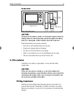
Instrument
D4644-2
Instrument dimensions
126 mm (5.0 in)
21 mm
(0.8 in)
17 mm
(0.67 in)
55 mm
(2.2 in)
70 mm
(2.8 in)
30 mm (1.2 in)
minimum cable clearance
ST40
CAUTION:
The presence of moisture at the rear of the instrument could cause
damage either by entering the instrument through the breathing
hole or by coming into contact with the electrical connectors.
Each instrument must be positioned where:
• It is easily read by the helmsman or navigator
• It is protected against physical damage
• It is at least 230 mm (9 in) from a compass
• There is reasonable rear access for installation and servicing
• The rear of the instrument is protected from water.
3.2 Procedures
Adapt these procedures as appropriate, to suit your individual
requirement.
CAUTION:
Where it is necessary to cut holes (e.g. for cable routing and
instrument mounting), ensure that these will not cause a hazard by
weakening critical parts of the vessel’s structure. If in doubt, seek
advice from a reputable boat builder.
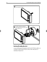
Fitting transducer
Instructions for installing and maintaining the speed transducer are
packed with it. Before attempting to install the transducer, read these
instructions and the
Site requirements
for transducers described in this
Chapter.
157_2c03.p65
01/05/01, 12:22
13
Содержание ST40 Speed
Страница 1: ...ST40 Speed Instrument Owner s Handbook Document number 81157 3 Date March 2006 ...
Страница 12: ...4 ST40SpeedInstrumentOwner sHandbook ...
Страница 28: ...20 ST40SpeedInstrumentOwner sHandbook ...
Страница 34: ...26 ST40SpeedInstrumentOwner sHandbook ...
Страница 36: ...28 ST40SpeedInstrumentOwner sHandbook ...
Страница 39: ...D4800 1 TOP Cut out shaded area only Cut out hole 57 mm 2 25 in diameter ST40 Instrument Template ...
Страница 40: ......