background image

Operation and Installation

7

damage the equipment, but may cause the loss of some information and may

change the operating mode.

• Raymarine specified cables are used at all times. Cutting and rejoining these

cables can compromise EMC performance and so must be avoided unless
doing so is detailed in the installation manual.

• If a suppression ferrite is attached to a cable, this ferrite should not be

removed. If the ferrite needs to be removed during installation it must be

reassembled in the same position.

The following illustration shows typical cable suppression ferrites fitted to

Raymarine equipment. Always use the ferrites supplied by Raymarine.

D3548-2

Connections to Other Equipment

If your Raymarine equipment is to be connected to other equipment using a
cable not supplied by Raymarine, a suppression ferrite MUST always be fitted

to the cable close to the Raymarine unit.

EMC Conformance

Always check the installation before going to sea to make sure that it is not

affected by radio transmissions, engine starting etc.

166_3chs.p65

24/01/02, 11:21

7

Содержание RS232

Страница 1: ...PC SeaTalk NMEA InterfaceBox Owner s Handbook Documentnumber 81166 3 Date 1February2002...

Страница 2: ...Copyright Raymarine Limited 2002...

Страница 3: ...pter 1 Introduction 3 Chapter 2 Mounting 4 Chapter 3 Operation Wiring 6 3 1 NMEA Output 6 3 2 NMEA Input 9 3 3 Main Alarm 12 3 4 Connecting to a Personal Computer 14 3 5 Connecting to a PC with RayTec...

Страница 4: ...ned to the best industry standards for use in the leisure marine environment The design and manufacture of Raymarine equipment and accessories conform to the appropriate Electromagnetic Compatibility...

Страница 5: ...conversion between SeaTalk RayTech PC and NMEA 0183 data formats allows operation with other manufacturer s equipment and with PCs The PC SeaTalk NMEA Interface provides Connection of SeaTalk to a PC...

Страница 6: ...ter clean and grease free accessible for cabling reasonably well protected from physical damage 1 Once a suitable location has been found thoroughly clea n the surface with an alcohol based cleaner 2...

Страница 7: ...ttached using the 2 self tapping screws provided 4 Remove the top of the Interface box by squeezing the lid at each end and pull away from the base 5 Route all the necessary cables into the Interface...

Страница 8: ...notbepossibletomeetallofthese conditionsinallsituations ToensurethebestpossibleconditionsforEMC performancewithintheconstraintsimposedbyanylocation alwaysensurethe maximumseparationpossiblebetweendiff...

Страница 9: ...oved Iftheferriteneedstoberemovedduringinstallationitmustbe reassembledinthesameposition Thefollowingillustrationshowstypicalcablesuppressionferritesfittedto Raymarineequipment Alwaysusetheferritessup...

Страница 10: ...itted NMEA Header Apparent Wind Angle MWV VWR Apparent Wind Speed MWV VWR Bearing to Waypoint BWC APB Course Over Ground M VTG Cross Track Error APB XTE Date ZDA Depth DBT Distance Log VLW Distance Tr...

Страница 11: ...Temperature Water MTW Time ZDA Time Offset ZTG TrueWindAngle MWV VWT True Wind Direction MWD True Wind Speed MWV VWT MWD Variation HDG Waypoint Capture WPL Velocity Made Good to Wind VPW Waypoint Capt...

Страница 12: ...x Cabling The PC SeaTalk NMEA Interface should be connected to SeaTalk and the other manufacturer s equipment as follows D1771 2 Screen 0v Yellow Data Red v Red v Screen 0v Power 5A NMEA SEATALK ALARM...

Страница 13: ...it is already on present on the SeaTalk bus Data Received NMEA Header Apparent Wind Angle MWV VWR Apparent Wind Speed MWV VWR Bearing to Waypoint APB BWR BWC RMB BER BEC Course Over Ground M VTG VTA R...

Страница 14: ...C RMA IMA GLP GOP GXP GDP MOB Cancel PNATA Route WPL Speed Over Ground VTG VTA RMC RMA Speed Through water VHW Temperature Water MTW Time ZDA GLL ZFO ZTG TrueWindAngle MWV Variation HDG HVM RMC RMA HV...

Страница 15: ...Operation and Installation 13 Cabling ST1 2 3000 autopilots D5509 1 Screen 0v Yellow Data Screen 0v NMEA SEATALK ALARM OUT IN OUT RS232 SEATALK NMEA Red 12V 5A Fuse...

Страница 16: ...Deep Depth Shallow Depth Autopilot off course Watch alarm Wind shift Lowbattery LargeCrossTrackError No NMEA data NMEADataerror No autopilot Main power No autopilot actuator Drive stopped Radar Guard...

Страница 17: ...ion 15 Cabling The Main Alarm should be wired to the PC SeaTalk NMEA Interfaceasfollows NMEA SEATALK ALARM OUT IN OUT RS232 SEATALK NMEA D1769 2 Screen 0v Yellow Data Red v Red v Screen 0v Power 5A Ma...

Страница 18: ...e can be used to send or receive SeaTalk and NMEA data to or from a personal computer via the RS232 OUT and NMEA IN terminals as shown in the following illustrations NMEA SEATALK ALARM OUT IN OUT RS23...

Страница 19: ...Operation and Installation 17 NMEA SEATALK ALARM OUT IN OUT RS232 SEATALK NMEA D1773 2 Red v Screen 0v Power 5A Screen 0v Red v Yellow Data Ground Receive...

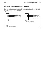
Страница 20: ...MEA The following diagram shows the pin connections for 25 pin and 9 pin PC serial ports to NMEA 2 RS232 Ground Receive into PC Receive into PC Transmit from PC Transmit from PC 3 7 2 RS232 Ground 3 5...

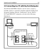
Страница 21: ...ersonal computer equiped with RayTech Navigator charting software Connection is via the RS232 OUT and NMEA IN terminals as shown in the following illustration Direct SeaTalk Interface E85001 NMEA SEAT...

Страница 22: ...ect betweentheInterfacebox andthepowersupply NMEAdatanotconverted Equipmentnotsetupto Refertothemanufacturers andtransmittedontothe transmitcorrectNMEA operatinghandbook SeaTalkbus sentences Interface...

Страница 23: ...tricalequipmenttointeractwithone another withaconsequentadverseeffectonoperation Inordertominimise theseeffectsandenableyoutogetthebestpossibleperformancefromyour Raymarineequipment guidelinesaregiven...

Страница 24: ...22 PC SeaTalk NMEA Interface Box...

Отзывы: