


Chapter 2: Installation
2-3
Surface Mounting
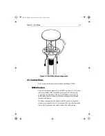
Refer to Figure 2-1 :
1. Select a suitable area which allows access to the underside of the
mounting surface for fixing and, using the template supplied in
this document, carefully drill the two 6mm (0.25in) fixing holes
marked.
2. If the cable is to pass through the mounting surface drill the 6mm
(0.25in) or 19mm (0.75in) centre hole depending on whether the
plug is to pass through the surface or not.
If the cable is to exit from the side of the GPS Receiver above the
mounting surface, remove the two plastic tabs (1) obstructing the
cable channel.
Note: Failure to remove the plastic tabs from within the cable chan-
nel could result in cable damage.
3. Screw the supplied brass studs (2) into the underside of the GPS
Receiver.
4. Stick the supplied gasket (3) to the mounting surface ensuring that
the holes match and pass the cable through the centre hole or the
cable exit channel.
5. Carefully position the GPS Receiver, passing the studs through
the holes in the mounting surface and secure to the mounting sur-
face using the thumb nuts provided (4).
81170_2.BOOK Page 3 Thursday, July 19, 2001 2:36 PM
Содержание RAYSTAR 120
Страница 2: ...81170_2 BOOK Page ii Thursday July 19 2001 2 36 PM...
Страница 6: ...vi Raystar 120 GPS Receiver 81170_2 BOOK Page vi Thursday July 19 2001 2 36 PM...
Страница 22: ...A 2 Raystar 120 GPS Receiver 81170_2 BOOK Page 2 Thursday July 19 2001 2 36 PM...
Страница 24: ...B 2 Raystar 120 GPS Receiver 81170_2 BOOK Page 2 Thursday July 19 2001 2 36 PM...
Страница 26: ...81170_2 BOOK Page 2 Thursday July 19 2001 2 36 PM...