Raymarine RAYSTAR 120 Скачать руководство пользователя страница 14

2-2

Raystar 120 GPS Receiver

2.2 Installation Procedure

Before commencing installation ensure you have the correct unit for
your application. Appendix B identifies the correct version of the
Raystar 120 GPS Receiver for compatible Raymarine, Autohelm and
Apelco units.

Raymarine cannot be responsible for incorrect operation due to
incorrect unit specification. Always state which model you have
when making any communication with Raymarine or a registered
service agent.

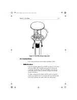
GPS Receiver Installation

The Raystar 120 GPS Receiver is designed to receive the signals
emitted from the satellites in a direct path. Ideally, the unit should be
mounted horizontally in a location that is open and clear of any masts,
search lights, or other structures that could block line-of-sight
reception of signals. The height of the GPS Receiver is not as
important as it’s having a clear view horizon to horizon for optimum
signal reception. In fact, the lower the unit can be mounted and have a
clear view to satellites, the better. The more stable the unit, the easier
it is to track satellites lower to the horizon.

The Raystar 120 can be mounted on a pole. Alternatively, you can use
the supplied surface mount kit.

When mounting the GPS Receiver flush to a deck surface, avoid
areas where the unit will be trodden upon or where it may present a
tripping hazard.

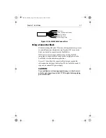
When planning the location for the unit, consider finding a
convenient pathway for running the interconnecting cable between
the GPS Receiver and the display unit or to the rest of an integrated
system. Ideally the cable should be run in a manner such that it is
hidden from view and, if possible, be in a direct path to the point of
connection. It is important to keep the cable separated from other
shipboard cables as far as possible to prevent interference pick-up.

Note: Mounting on the mast of a sailboat is not recommended.

81170_2.BOOK Page 2 Thursday, July 19, 2001 2:36 PM

Содержание RAYSTAR 120

Страница 1: ...Raystar 120 GPS Receiver Owner s Handbook Document 81170_2 Date July 2001 81170_2 BOOK Page i Thursday July 19 2001 2 36 PM...

Страница 2: ...81170_2 BOOK Page ii Thursday July 19 2001 2 36 PM...

Страница 3: ...st distributor for service 2 NAVIGATION AID This device is only an aid to navigation Its accuracy can be affectedbymany factors including equipmentfailureordefects environmental conditions and imprope...

Страница 4: ...ce All Raymarine equipment and accessories are designed to the best industry standards for use in the recreational marine environment The design and manufacture of Raymarine equipment and accessories...

Страница 5: ...ing your Raystar 120 Package 1 4 Package Contents 1 4 Items Missing 1 4 1 3 Registering this Product 1 4 EMC Servicing and Safety Guidelines 1 5 Technical Summary 1 6 Chapter 2 Installation 2 1 2 1 EM...

Страница 6: ...vi Raystar 120 GPS Receiver 81170_2 BOOK Page vi Thursday July 19 2001 2 36 PM...

Страница 7: ...by the Federal Aviation Administration FAA 2 European Geostationary Navigation Overlay System EGNOS This system is being developed by a European con sortium 3 The MTSAT Satellite Based Augmentation S...

Страница 8: ...nce Stations are located at known positions and receivedatacontinuouslyfromGPS The GroundReferenceStations send their data to the Master Stations which calculate the error of the GPS received position...

Страница 9: ...ebsite http wwws raytheontands com waas or at Raymarine s website http www raymarine com Coverage Outside of North America EGNOS is currently in the early testing and qualification phases and signal o...

Страница 10: ...utilized 1 2 Checking your Raystar 120 Package Package Contents The Raystar 120 package contains the following standard items 1 Low profile GPS Receiver 2 Flush mount gasket 3 Mounting studs Thumb nu...

Страница 11: ...nteract with one another with a consequent adverse effect on operation In order to minimise these effects and ensure the best possible performance from your Raymarine equipment guidelines are given in...

Страница 12: ...2 5 minutes maximum typically 40 seconds Position accuracy 15m RMS L1 C A code HDOP 2 5 without SA Speed accuracy 0 5m s RMS L1 C A code HDOP 2 5 without SA Geodetic Datum WGS 84 190 programmable alte...

Страница 13: ...mum EMC performance it is recommended that wherever possible Raymarine equipment and cables connected to it are At least 3 ft 1 m from any equipment transmitting or cables carrying radio signals e g V...

Страница 14: ...a clear view horizon to horizon for optimum signalreception In fact thelowertheunitcan bemounted andhavea clear view to satellites the better The more stable the unit the easier it is to track satell...

Страница 15: ...t from the side of the GPS Receiver above the mounting surface remove the two plastic tabs 1 obstructing the cable channel Note Failure to remove the plastic tabs from within the cable chan nel could...

Страница 16: ...e centre hole B or insert the cable into the side exit channel C 3 Check the cable is positioned correctly and secure the GPS Receiver to the pole mount base using the two screws provided If the cable...

Страница 17: ...ulded 6 pin connector Alternatively connection can be made to other types of NMEA connector The cable can be cut as necessary to the required length or coiled and stored out of the way If you have equ...

Страница 18: ...ted and taped back Connectionismadeviaa33ft 10m cableterminatedwithamoulded 6 pin connector as detailed in Figure 2 3 Figure 2 3 NMEA Connector Pin outs SeaTalk Version Connection is made via the 10m...

Страница 19: ...tor block can be used to supply power to the SeaTalk bus for this and other applications Figure 2 5 shows how the connector block is used to make the interconnections between the RayStar 120 the SeaTa...

Страница 20: ...ittheRaymarinewebsite at www raymarine com Table 2 2 NMEA Sentences Output Sentences Input Sentences GPGGA GPRMC PRAYI GPGSA GPDTM PRAYE GPGSV GPVTG PRAYA GPGLL Wire colour Screen Red Yellow Black Red...

Страница 21: ...ss to the underside of the mounting surface must be available to allow for se cure fixing Figure A 1 Mounting Template Cable Exit Channel 18mm 0 7in 6mm 0 25 dia for cable only 19mm 0 75 dia for NMEA...

Страница 22: ...A 2 Raystar 120 GPS Receiver 81170_2 BOOK Page 2 Thursday July 19 2001 2 36 PM...

Страница 23: ...rine Autohelm and Apelco units Please use Table B 1 to confirm that you are installing the correct version of Raystar 120 Table B 1 Application Cross Reference Raystar 120 NMEA Part E32026 Raystar 120...

Страница 24: ...B 2 Raystar 120 GPS Receiver 81170_2 BOOK Page 2 Thursday July 19 2001 2 36 PM...

Страница 25: ...STRICTED RIGHTS The Software and Documentation are provided with Restricted Rights Use duplication or disclosure by the Government is subject to restric tions asset forth in thisAgreement pursuantto D...

Страница 26: ...81170_2 BOOK Page 2 Thursday July 19 2001 2 36 PM...

Отзывы: