background image


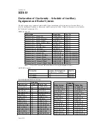
Sheet 1 of 2 


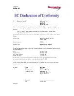
Certificate No. 

RT041 


We 

Raymarine Limited 

Anchorage Park 

 Portsmouth 
 Hampshire 
 England 

P03 

5TD 

declare, under our sole responsibility, that the products identified in this declaration, and to which this 
declaration relates, are in conformity with the essential requirements of European Parliament and Council 
Directive: 

1999/5/EC on radio equipment and telecommunication terminal equipment and the mutual 
recognition of their conformity. 

Specifically this declaration includes conformity to ITU Radio Regulations on Unwanted Emissions of Radar 
Systems. 

 
Product Name: 

Raymarine 10kW Open Array 

 Scanner 

Unit 

 
Product Number(s): 

M92655, from S/n 0332000 


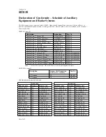
Ancillary Units 

C-series Displays - details given on Sheet 2 


The products have been assessed to Conformity Procedure Annex IV of the Directive and by application of the 
following standard(s): 

EMC 

EN 60945 : 2002 

Health & Safety


EN 60945 : 2002 

Out of  Band Emissions 

ITU-R M1541 

Spurious Emissions 

ITU-R M1177-2 

 
The assessment is consistent with a Technical Construction File showing conformity with the essential 
requirements of the Directive and has been reviewed by Notified Body No

.

 0191


The product is labelled with the CE conformity marking, the identification number of the Notified Body and 
class identifier. 


Signatory: Name 

Adil Abbas 


Title 

International Compliance Manager 


Company Name 

Raymarine Limited 


Company Address 

Anchorage Park 


Portsmouth, Hampshire 


England  PO3 5TD


Signature _________________________ 

 Date 


13 

February 

2004 

Содержание Pathfinder Radar Scanners

Страница 1: ...Pathfinder Radar Scanners Owner s Handbook Document number 81154_9 Date September 2006...

Страница 2: ......

Страница 3: ...adar scanner transmits electromagnetic energy It is important that the radar is turned off whenever personnel are requiredtocomeclosetothescannertoperformworkonthescannerassemblyor associated equipmen...

Страница 4: ...mited Anchorage Park Portsmouth Hampshire PO3 5TD England Telephone 44 0 23 9269 3611 Fax 44 0 23 9269 4642 www raymarine com Copyright Raymarine Ltd 2006 The technical and graphical information conta...

Страница 5: ...Technical Support representatives or your local dealer will be available to answer any questions you may have Display Software Version For full operation of the Pathfinder scanners the display unit r...

Страница 6: ...rd to the factory in order to receive full warranty benefits The radome scanner package includes a barcode label indicating the serial number of the unit This label should be stuck to the warranty reg...

Страница 7: ...duct Number s M92654 Ancillary Units Details are given on Sheet 2 The products have been assessed to Conformity Procedure Annex IV of the Directive and by application of the following standard s EMC E...

Страница 8: ...RL70CRC PLUS E52034 E52034HB Display Unit 10 Colour LCD hsb RL80C PLUS E52037 Display Unit 10 Colour LCD hsb Chart RL80CRC PLUS E52038 Note 7 Colour LCD Units with HB suffix Part No s have higher brig...

Страница 9: ...Product Number s M92655 Ancillary Units Details are given on Sheet 2 The products have been assessed to Conformity Procedure Annex IV of the Directive and by application of the following standard s EM...

Страница 10: ...E52034HB Display Unit 10 Colour LCD hsb RL80C PLUS E52037 Display Unit 10 Colour LCD hsb Chart RL80CRC PLUS E52038 Note 7 Colour LCD Units with HB suffix Part No s have higher brightness displays ANT...

Страница 11: ...S n 0132000 Ancillary Units C series Displays details given on Sheet 2 The products have been assessed to Conformity Procedure Annex IV of the Directive and by application of the following standard s...

Страница 12: ...to form the operational radar systems Details of these units are included in the Technical Construction File DISPLAY one of Description Designation Part No Display Unit 7 Colour LCD Chart C70 E02018 D...

Страница 13: ...S n 0332000 Ancillary Units C series Displays details given on Sheet 2 The products have been assessed to Conformity Procedure Annex IV of the Directive and by application of the following standard s...

Страница 14: ...to form the operational radar systems Details of these units are included in the Technical Construction File DISPLAY one of Description Designation Part No Display Unit 7 Colour LCD Chart C70 E02018 D...

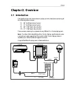
Страница 15: ...ay Scanner These scanner units may be connected to any HSB hsb2 or C Series display unit Note To achievefull compatibility with a C SeriesDisplay yourRaymarine radar scanner may require upgrading Plea...

Страница 16: ...nvironment Their design and manufacture conforms to the appropriate Electromagnetic Compatibility EMC standards but correct installation is required to ensure that performanceisnotcompromised Although...

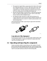
Страница 17: ...e removed Iftheferriteneedstoberemovedduringinstallationitmustbereas sembled in the same position Section 2 1 Radome scanner includes instruc tions on fitting a ferrite The following illustration show...

Страница 18: ...ove the waterline for three reasons For safety reasons the scanner should be out of range of personnel pref erably above head height This avoids mechanical danger and electro magnetic contact particul...

Страница 19: ...al plane can interfere with the radar signal and cause blind areas or shadow sectors and false targets on the radar screen see below However do not mount the scanner so high that it is affected by the...

Страница 20: ...4 in 427 mm 16 8 in 296 mm 11 65 in 406 mm 16 in D4572 4 Weight Pedestal 24 kg 53 0 lb 48 Open Array 6 kg 13 2 lb 72 Open Array 9 4 kg 20 7 lb 140 mm 5 5 in Minimum clearance height 510 mm 20 1 in 150...

Страница 21: ...ectorsthebeamintensitymaynotbesufficienttoobtainan echo from a very small object even at close range despite the fact that a large vessel can be detected at a much greater range For this reason the an...

Страница 22: ...aflat surface on a mast with a minimum diameter of 60 mm 2 in When using the mast mount kit appropriate hardware should be used for the style and structure ofthemastaboardthevessel Typically thescanne...

Страница 23: ...theradar smainradiationplane andcancausepoordetectionof nearby targets It may be helpful to lower the radar beam back towards the parallel by shimming the rear of the radar so that the beam points sli...

Страница 24: ...er to the notes below Scanner Cables Thecableusedtoconnectyourscannertothe displayunitandpowerdependson the type of scanner and display as follows A radome scanner connected to a Pathfinder or C Serie...

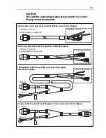
Страница 25: ...thfinder displays Split pedestal cable for use with new open array scanner and C Series display Adaptor cable for use with existing open array scanner and C Series display To display or extension powe...

Страница 26: ...e type contact Raymarine for details Take care not todamageany of the wires Make surethat allthe wiresand in particular the screen are reconnected correctly Ifyouaremountingthescanneronthemastofasailb...

Страница 27: ...t be used directly with 12 V systems they require a 12 V to 24 V converter rated to 180 W Contact your authorized Raymarine dealer or distributor for details 12 V Systems 4 kW scanners only For vessel...

Страница 28: ...Raymarine dealer or distributor for details Open array scanners draw considerable power from the vessels power source especially in high wind speeds It is essential forreliable operation that the unit...

Страница 29: ...e battery isolator switch via its own dedicated cable system CAUTION The display unit does not include a fuse for scanner power so an in line fuse or circuit breaker MUST be included in the power cabl...

Страница 30: ...avy 10 5 14 0 18 0 28 0 15 m Heavy 9 0 12 0 16 0 24 0 15 m Heavy 5 m ext 7 5 10 0 13 0 20 0 15 m Heavy 10 m ext 6 0 8 0 10 0 16 0 25 m Heavy 6 0 8 0 10 0 16 0 25 m Heavy 5 m ext 4 5 6 0 8 0 12 0 25 m...

Страница 31: ...tion 15m cableprovides 15m from scanner to Y junction These lengths should be sufficient to complete the cable run required on most small vessels Pedestal adaptor cable Thepedestaladaptorcablecombines...

Страница 32: ...ction Power Connections The power connection to the radar should be made at either the output of the battery isolator switch or at a DC power distribution panel Raymarine recommends that power is fed...

Страница 33: ...rmal Breaker rating 8 A 10 A 5 A Fuse value 10 A 15 A 8 A 10 kW scanners cannot be directly connected to 12 V Radome systems cannot use 32V Table 2 7 Isolator Switch Thermal Breaker Fuse Value Vessels...

Страница 34: ...cciv...

Страница 35: ...ccv...

Страница 36: ...ccvi...

Страница 37: ...is fitted The pedestal base is fitted with a seal DO NOT grease this seal WARNING The open array scanner weighs 48 scanner 30 kg 66 2 lb 72 scanner 33 4 kg 73 7 lb For safety reasons it is recommende...

Страница 38: ...eachstudintothepedestaltoa maximum of 32 mm or until they bottom out Remove these two nuts Note Ifthestudding suppliedis notlong enough useM10stainless steel gradeA4 70 studding of asuitable length Re...

Страница 39: ...ote Itisimportanttoremoveliftingeyestoavoidcorrosion Retaintheliftingeyes they willberequired if the scanner is removed fromits platform 2 Open the pedestal lid Ensure the securing stay has automatica...

Страница 40: ...pedestal base using the plastic cable clamp Hand tighten the cable gland nut 6 The cable is supplied prepared and ready to fit to the signal and power con nectors If you need to cut the cable to lengt...

Страница 41: ...th 5 6 mm strip length 5mm maximum 25 mm 35 mm 25 mm 35 mm 1 Preparation of Wires 2 Heat Shrinking of Wires 3 Preparation of Earthing Braid Apply heatshrink ensuring at least 15 mm of braid is visible...

Страница 42: ...d is correctly seated Grease the four self retaining case bolts and thread holes with Denso paste supplied Close the pedestal lid ensuring that the cable does not become trapped and that the seal is n...

Страница 43: ...ed CAUTION If the pin is damaged during the following operation you should contact your service dealer 3 Lifttheopenarrayintoposition Carefullylowerthearray topreventdamage to the mounting pin ensure...

Страница 44: ...tifies the scanner connector on the various display connector panels If you are usingan inter unitextension cable connectthis tothe display unit and connect the supplied cable to the extension cable Y...

Страница 45: ...or if any personnel are in the vicinity of the open array the switch should be set to OFF Y G SeaTalk TRANSDUCER POWER NMEA HSB NMEA OUT R NMEA IN OUT DSM SEATALK RADAR SEATALK 2 SEATALK 2 R G Y POWER...

Страница 46: ...igger Battery ve Data I O Battery ve Azimuth Azimuth 1 2 3 4 5 6 7 8 9 10 11 12 13 8 7 6 5 4 3 2 1 8 7 6 5 4 3 2 1 White Black Orange Yellow Green Blue Purple Grey Red Red Black Black Video Video Rtn...

Страница 47: ...ted Azimuth Azimuth 1 2 3 4 5 6 7 8 9 10 11 12 13 8 7 6 5 4 3 2 1 8 7 6 5 4 3 2 1 White Black Orange Yellow Green Blue Purple Grey Red Black Red Black Green Power Video Video Rtn Tx Trigger Tx Trigger...

Страница 48: ...ccxviii...

Страница 49: ...ccxix...

Страница 50: ...ccxx...

Страница 51: ...ccxxi...

Страница 52: ...ccxxii...

Страница 53: ...lation before going to sea to make sure that it is not affected by radio transmissions engine starting etc 4 1 System Checks and Alignment System check Before performing the functional test check the...

Страница 54: ...f the cable used to connect the scannertothedisplayunit Thisinturnaffectstheshortrangeaccuracyshownon the display It is advisable to check the display timing before using the system for navigation 72...

Страница 55: ...eck that the cable connectors are firmly attached Make sure the scanner and pedestal are still attached securely to the mount ing Once a year remove grease and re attach the mounting bolts securing th...

Страница 56: ...dentifythemostlikelycause and the corrective action required to restore normal operation If you still have a problem after referring to the table below contact your local dealer national distributoror...

Страница 57: ...teforthelatestinformationonthenewest Raymarine electronic equipment and systems at www raymarine com For Accessories and Parts Many Raymarine accessory items and parts can be obtained directly from yo...

Страница 58: ...cknowledging therepairstatusand the product sreferencenumber Should youwishtoinquireabouttherepairstatusofyourunit contacttheProductRepair Center at 1 800 539 5539 extension 2118 Please have theproduc...

Страница 59: ...o choose for your Raymarine unit please contact our Customer Services Department prior to placing your order Worldwide Support Please contact the authorized distributor in the country A list of worldw...

Страница 60: ...ccxxx...
Страница 61: ...ion 100 Kts Maximum Range Scale 72 nm 5S Transmitter 4 kW Input Voltage 10 7 44 V DC from display unit Power Consumption 9 2 W Standby 46 W Typical operation in light winds 61 W Max operation in 50 Kt...

Страница 62: ...0 MHz Peak Power Output 10 kW nominal Transmitter Solid state modulator driving magnetron Pulse Length PRF Normal Expanded Range nm Pulse Length S PRF Hz Bandwidth MHz Pulse Length S PRF Hz Bandwidth...

Страница 63: ...array scanner fea tures 48 Antenna Antenna Type Slotted waveguide array Beam Width nominal 1 85 Polarization Horizontal Antenna Side lobes Less than 22 dB Rotation Rate 24 rpm nominal Receiver IF Fre...

Страница 64: ...4 kW Input Voltage 10 7 44 V DC from display unit Power Consumption 9 2 W Standby 46 W Typical operation in light winds 83W Max operation in 50 Kt winds 135W Max operation in 100 Kt winds min input vo...

Страница 65: ...ing magnetron Pulse Length PRF Normal Expanded Range nm Pulse Length S PRF Hz Bandwidth MHz Pulse Length S PRF Hz Bandwidth MHz 0 125 0 065 3000 12 0 09 3000 12 0 25 0 065 3000 12 0 09 3000 12 0 50 0...

Страница 66: ...t for the latest display software to ensure you can use all the open array scanner fea tures Receiver IF Frequency 60 MHz nominal Receiver Characteristic Semi log Receiver Noise Figure Less than 5 dB...

Отзывы: