ccxvi
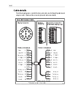
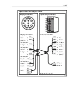
Cable details
The following diagrams - one for the inter-unit cable, one for the split pedestal and
adaptor cable - illustrate the connector pins and cable core details.
1
2
3
5
4
7
10
11
8
6
9
13
12
Black
White
Orange
Black
Black
Green
Yellow
Shield
Red
Red
Violet
Blue
Grey
Video
Video RTN
*
Battery --ve
Tx T
Battery --ve
Data I/O +
Tx Trigger --
Bve
Data I/O --
*
Bve
A
Azimuth --
1
2
3
4
5
6
7
8
9
10
11
12
13
8
7
6
5
4
3
2
1
8
7
6
5
4
3
2
1
White
Black
Orange
Yellow
Green
Blue
Purple
Grey
Red
Red
Black
Black
Video
Video Rtn
Tx T
Tx Trigger --
Data I/O +
Data I/O --
A
Azimuth --
Bve
*
Bve
*
Battery --ve
Battery --ve
Radome
Connector
Open Array Connector
(Pathfinder display only)
Display Connector
Inter-Unit Scanner Cable
Display connections
Scanner connections
*
Not present on 'light', 11 core cables.
Bve/--ve = 12 or 24v.
D4290-4
2
1
4
3
6
5
8
7
Содержание Pathfinder Radar Scanners
Страница 1: ...Pathfinder Radar Scanners Owner s Handbook Document number 81154_9 Date September 2006...
Страница 2: ......
Страница 34: ...cciv...
Страница 35: ...ccv...
Страница 36: ...ccvi...
Страница 48: ...ccxviii...
Страница 49: ...ccxix...
Страница 50: ...ccxx...
Страница 51: ...ccxxi...
Страница 52: ...ccxxii...
Страница 60: ...ccxxx...

