Raymarine E12139 Скачать руководство пользователя страница 19


19

5. Post-installation check


Check the following points after installing the pump:

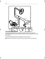
1. Is the pump installed in such a way that hose lengths are kept to a minimum?
2. Is the pump secured to a substantial structure on the boat?
3. Have you connected a reservoir pipe between the helm pump and autopilot pump?
4. Have you fitted check valves where appropriate?
5. Are the hydraulic pipes made of a suitable flexible material (i.e. rubber or nylon) with a 

suitable pressure rating?

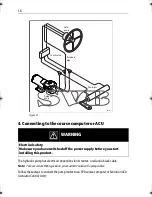
6. Are power cables correctly routed and securely connected to the course computer or 

ACU?

You have now finished installing the pump. After installing the rest of the autopilot you must 
bleed all air from the system (see below). 

Note:  

When you have installed the entire autopilot system, you will also need to complete an autopilot 

steering check. Refer to the control unit handbook for more details. 

Bleeding the system

Bleeding the hydraulic system correctly is one of the most important steps when installing the 
autopilot hydraulic pump. If there is any air in the system the steering will feel unresponsive, 
particularly when you turn the wheel to hardover.

IMPORTANT: 

Any air in the hydraulic system will greatly reduce the performance of the 

autopilot and the overall steering system.

Follow the 

helm

 pump manufacturer’s instructions to fill the hydraulic hoses so that the A, B 

& R hoses do not contain trapped air or air bubbles. The hose connections to the pump may 
need to be loosened to allow air to escape. The pump can now be run. Follow the set up 
instructions for your autopilot control head. If the pump runs but the rudder does not move, 
use the autopilot control head to initiate a course correction. This will start the pump. 
Manually turn the helm wheel in the same direction as the course correction. This forces fluid 
into the pump, displacing any residual air.

In addition to the manufacturer’s instructions for bleeding the steering system, follow these 
steps to bleed the autopilot pump once you have installed and set up the rest of the autopilot 
system:


WARNING

Steering systems
Keep clear of moving steering systems at all times. Protect moving parts 
from access during normal use. 

81178_5.book  Page 19  Wednesday, April 24, 2013  6:42 PM

Содержание E12139

Страница 1: ...5 Hydraulic Pump 12 V M81120 Type 1 Hydraulic Pump 12 V M81119 Type 1 Hydraulic Pump 24 V M81121 Type 2 Hydraulic Pump 12 V M81123 Type 2 Hydraulic Pump 24 V M81122 Type 3 Hydraulic Pump 12 V M81124...

Страница 2: ...nce personal injury and or damage to your boat Because correct performance of the boat s steering is critical for safety we STRONGLY RECOMMEND that an Authorized Raymarine Service Representative fits...

Страница 3: ...uct is supplied from a separate battery from that used for engine start This is important to prevent erratic behavior and data loss which can occur if the engine start does not have a separate battery...

Страница 4: ...the recyclingofwasteelectricalandelectronicequipment WhilsttheWEEE Directive doesnotapplytosomeofRaymarine sproducts wesupportitspolicyandaskyou to be aware of how to dispose of this product The cross...

Страница 5: ...gulations Technical accuracy To the best of our knowledge the information in this handbook was correct when it went to press However Raymarine cannot accept liability for any inaccuracies or omissions...

Страница 6: ...entmagnet motors The pumps include pilot operated check valves that prevent the pump being back driven by the manual steering system or rudder load The motors have an IP67 rating and can be removed fr...

Страница 7: ...Maximum intermittent pressure at 12 V 55 bar 800 psi Peak flow rate no load 600 cc min 36 6 in3 min 1000 cc min 61 0 in3 min 2300 cc min 140 4 in3 min 3100 cc min 189 2 in3 min Typical current at 12...

Страница 8: ...raulic pipes hydraulic fluid T pieces and pipe fittings see page11 suitable securing bolts and lock nuts see page10 cable and electrical connectors for the drive motor see page16 Table 1 2 Pump dimens...

Страница 9: ...tched off the power supply before you start installing this product 1 Consult the EMC installation guidelines page3 2 Mount the pump page10 3 Connect to the hydraulic steering system page11 4 Connect...

Страница 10: ...immersion level or above the hydraulic steering ram to prevent air collecting in the ram as close to the ram as possible Orientation The pump can be mounted in any orientation If mounting vertically...

Страница 11: ...ons CAUTION Pump connection Before you connect the autopilot pump to your hydraulic system we strongly recommend that you consult the steering gear manufacturer CAUTION Hydraulic systems Absolute clea...

Страница 12: ...essed by removing the blanking plug All pipes used to fit the pump should match or exceed the specification of the existing steering system pipes Contact the steering system manufacturer if you need m...

Страница 13: ...systems three line systems On the following pages typical connection points are described for the autopilot pump on each of these systems For all of the systems you will need to connect a third hydra...

Страница 14: ...ility of introducingairintothe systemand reducesany steering sponginess causedby pipe expansion Connect the autopilot pump to the steering system as shown in Figure 7 Note Referto the manufacturer s i...

Страница 15: ...eturning from the other side of the ram to the reservoir via a common return line Thesystemwillincludeacheckvalveblocktodirectallreturnedfluidfromtherambacktothe reservoir Connect the autopilot pump t...

Страница 16: ...EMClegislation youmustNOT untwist the pump cables Follow these steps to connect the pump motor to an SPX course computer or Evolution ACU Actuator Control Unit WARNING Electrical safety Make sure you...

Страница 17: ...erminal You will check these connections after installing the rest of the autopilot system Note Ifinstallingthepumponaboatwithmechanicalsteering youneedtoconnectabypassvalveto theCLUTCHterminals seepa...

Страница 18: ...valvetotheCLUTCHterminalsonthecoursecomputerorACUusing at least 1 5 mm2 16 AWG copper cable Note Followthe manufacturer s instructions for mounting thehydraulicramand reservoir Figure 10 Type 2 drive...

Страница 19: ...hydraulic pump If there is any air in the system the steering will feel unresponsive particularly when you turn the wheel to hardover IMPORTANT Any air in the hydraulic system will greatly reduce the...

Страница 20: ...p 2 Clear any air on the other side of the pump press the 10 button ten times the autopilot will try to drive the rudder to starboard counter the rudder movement by turning the helm to port continue u...

Страница 21: ...raulic system 1 Undo the two M6 socket head cap screws 5 mm AF allen key and remove the motor coupling and water seal O ring 2 If the coupling is worn or damaged it will need to be replaced Lubricate...

Страница 22: ...nt itemsof equipment i e ensure opti mum Electromagnetic Compatibility EMC AlwaysreportEMC relatedproblemstoyournearestRaymarinedealer Weusesuchinformationto improve our quality standards Insome insta...

Страница 23: ...butors and Authorized Service Representatives If you encounter any difficulties with this product please contact eitheryournationaldistributor oryourservicerepresentative ortheRaymarineTechnical Suppo...

Страница 24: ......

Отзывы: