background image

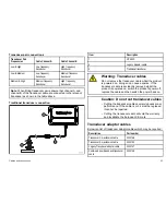
Warning: Sonar operation

• NEVER operate the sounder with the boat out of

the water.

• NEVER touch the transducer face when the sounder

is powered on.

• SWITCH OFF the sounder if divers are likely to be

within 7.6 m (25 ft) of the transducer.

Caution: Power supply protection

When installing this product ensure the power source
is adequately protected by means of a suitably-rated
fuse or automatic circuit breaker.

Caution: Do not cut transducer cables

• Cutting the transducer cable severely reduces sonar

performance. If the cable is cut, it must be replaced,
it cannot be repaired.

• Cutting the transducer cable will void the warranty

and invalidate the European CE mark.

General Information

Water ingress

Water ingress disclaimer
Although the waterproof rating capacity of this product meets the
IPX6 standard, water intrusion and subsequent equipment failure
may occur if the product is subjected to commercial high-pressure
washing. Raymarine will not warrant products subjected to
high-pressure washing.

EMC installation guidelines

Raymarine equipment and accessories conform to the appropriate
Electromagnetic Compatibility (EMC) regulations, to minimize
electromagnetic interference between equipment and minimize the
effect such interference could have on the performance of your
system

Correct installation is required to ensure that EMC performance is
not compromised.

For

optimum

EMC performance we recommend that wherever

possible:

• Raymarine equipment and cables connected to it are:

– At least 1 m (3 ft) from any equipment transmitting or cables

carrying radio signals e.g. VHF radios, cables and antennas.
In the case of SSB radios, the distance should be increased
to 7 ft (2 m).

– More than 2 m (7 ft) from the path of a radar beam. A radar

beam can normally be assumed to spread 20 degrees above
and below the radiating element.

• The product is supplied from a separate battery from that used

for engine start. This is important to prevent erratic behavior
and data loss which can occur if the engine start does not have
a separate battery.

• Raymarine specified cables are used.

• Cables are not cut or extended, unless doing so is detailed in

the installation manual.

Note: Where constraints on the installation prevent any of
the above recommendations

, always ensure the maximum

possible separation between different items of electrical
equipment, to provide the best conditions for EMC performance
throughout the installation

8

CP450C

Содержание CP450C

Страница 1: ...CP 4 5 0 C Cle a r P u ls e Ch ir p S o n a r Mo d u le Installation instructions ENGLISH Document number 87141 2 Date 03 2012 CP450C...

Страница 2: ......

Страница 3: ...s patents pending or design patents pending Fair Use Statement You may print no more than three copies of this manual for your own use You may not make any further copies or distribute or use the manu...

Страница 4: ......

Страница 5: ...Location and mounting 29 4 1 Selecting a location 30 4 2 Mounting 31 Chapter 5 System checks and troubleshoot ing 33 5 1 Initial power on test 34 5 2 Troubleshooting 34 5 3 Sonar troubleshooting 35 5...

Страница 6: ...6 CP450C...

Страница 7: ...plice transducer cables There is high voltage on the transducer cable Splicing could create a safety hazard Warning Switch off power supply Ensure the vessel s power supply is switched OFF before star...

Страница 8: ...tibility EMC regulations to minimize electromagnetic interference between equipment and minimize the effect such interference could have on the performance of your system Correct installation is requi...

Страница 9: ...ot apply to some Raymarine products we support its policy and ask you to be aware of how to dispose of this product Warranty registration To register your Raymarine product ownership please visit www...

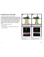
Страница 10: ...2 targets are close together they are shown as a single large target rather than multiple smaller targets By using a broadband swept frequency CHIRP the signal can distinguish between multiple close t...

Страница 11: ...installation Chapter contents 2 1 Handbook information on page 12 2 2 Installation checklist on page 12 2 3 CP450C system examples on page 13 2 4 Tools on page 17 2 5 Pack contents on page 17 Plannin...

Страница 12: ...cklist Installation includes the following activities Installation Task 1 Plan your system 2 Obtain all required equipment and tools 3 Site all equipment 4 Route all cables 5 Drill cable and mounting...

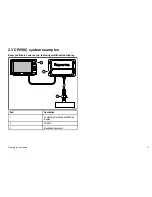
Страница 13: ...ystem examples Example Basic sonar set up featuring multifunction display D12225 1 1 2 3 Item Description 1 Compatible Raymarine multifunction display 2 CP450C 3 Broadband transducer Planning the inst...

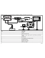
Страница 14: ...4 5 6 7 8 SeaT alkhs RayNet SeaT alkng D12226 1 3 Item Description 1 CP450C 2 Raymarine network switch 3 SeaTalkhs Crossover coupler required to connect to Raymarine HS5 Network switch 4 Digital rado...

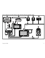
Страница 15: ...Example Extended sonar system featuring multiple multifunction displays and SeaTalkng network SeaT alkng SeaT alkhs RayNet 8 8 D12227 1 1 3 2 4 5 6 7 9 9 10 Planning the installation 15...

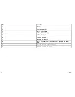
Страница 16: ...4 SeaTalkng Instrument display 5 SeaTalkng AIS receiver 6 Broadband transducer 7 Raymarine network switch 8 SeaTalkhs Crossover coupler required to connect to Raymarine HS5 Network switch 9 Compatibl...

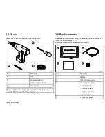
Страница 17: ...e of material that the unit is to be mounted on 2 5 Pack contents Unpack the unit carefully saving the packaging in case you need to return the unit for service Check that the correct components are p...

Страница 18: ...18 CP450C...

Страница 19: ...tions Chapter contents 3 1 General cabling guidance on page 20 3 2 Connections overview on page 21 3 3 Transducer connection on page 22 3 4 Network connection on page 24 3 5 Power connection on page 2...

Страница 20: ...it isolation Appropriate circuit isolation is required for installations using both AC and DC current Always use isolating transformers or a separate power inverter to run PC s processors displays and...

Страница 21: ...rk transducer and power cables to your unit 1 Ensure that the vessel s power supply is switched off 2 Ensure that the device being connected to the unit has been installed in accordance with the insta...

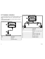
Страница 22: ...accordance with the instructions provided with the transducer Broadband transducer connection D12231 1 1 2 Item Description 1 CP450C 2 Broadband transducer Dual broadband transducer connections 1 5 6...

Страница 23: ...e the transducer cable whilst the product is powered on doing so can cause sparks If the transducer cable is accidently removed whilst the product is powered on switch the product s power off replace...

Страница 24: ...RayNet to RayNet network cable Multifunction display configuration extended cables A Raymarine crossover coupler and RayNet to SeaTalkhs RJ45 network cables should be used to extend the length of net...

Страница 25: ...for network connection of multiple SeaTalkhs devices featuring RayNet connectors Equipment with SeaTalkhs connectors can also be connected via suitable adaptor cables SeaTalkhs network switch E55058...

Страница 26: ...connecting SeaTalkhs devices to a Raymarine network switch via SeaTalkhs cables RayNet connector used for connecting Raymarine network switches and SeaTalkhs devices to the multifunction display via...

Страница 27: ...be mounted so that the power cable can be easily removed if necessary If the unit is placed in a difficult to reach location Raymarine recommends installing an on off switch on the power connection a...

Страница 28: ...t ensure it has been correctly grounded in accordance with the instructions in this guide Grounding Dedicated drain wire The power cable supplied with this product includes a dedicated shield drain wi...

Страница 29: ...Chapter 4 Location and mounting Chapter contents 4 1 Selecting a location on page 30 4 2 Mounting on page 31 Location and mounting 29...

Страница 30: ...r enough away from any equipment that may cause interference such as motors generators and radio transmitter receivers Magnetic compass mount the unit at least 1 m 3 ft away from a magnetic compass Po...

Страница 31: ...the required location using adhesive tape 108 2 mm 4 26 in 188 0 mm 7 40 in 34 6 mm 1 36 in 276 8 mm 10 90 in 299 4 mm 11 78 in Pilo t hol e cen ter 4 pos itio ns CS22 Te mplate UP IM PO RTAN T Th is...

Страница 32: ...s the measuremen ts prov ided Do cum ent num ber 871 42 1 Da te 07 201 1 Ra ym arine CS 22 digital so un de r mod ule mou nting template D1 219 7 1 D12241 1 3 Remove the mounting template 4 Screw in t...

Страница 33: ...eshooting Chapter contents 5 1 Initial power on test on page 34 5 2 Troubleshooting on page 34 5 3 Sonar troubleshooting on page 35 5 4 LED Diagnostics on page 37 5 5 Resetting the sonar on page 40 Sy...

Страница 34: ...operating instructions refer to the handbook that accompanies your multifunction display 5 2 Troubleshooting The troubleshooting information provides possible causes and corrective action required fo...

Страница 35: ...be inappropriate for present conditions Check the sounder presets gain and frequency settings Unit power supply fault Check the voltage from the power supply if this is too low it can affect the trans...

Страница 36: ...Possible causes Possible solutions Paddle wheel fault Check that the paddle wheel is clean No speed offset set Add speed offset Incorrect speed reading Incorrect calibration Re calibrate equipment 36...

Страница 37: ...Green shows the unit is operating normally Amber warns of a problem in the unit Red shows that there is an error in the unit The number of times the LED blinks is a code which represents the errors o...

Страница 38: ...oblem persists contact Raymarine technical support Amber 3 blinks Unit overheating Ensure installation environment is within recommendations Unit will recover when temperature falls within specificati...

Страница 39: ...bient temperature too hot Ensure installation environment is within recommendations Unit will recover when temperature falls within specifications If problem persists contact Raymarine technical suppo...

Страница 40: ...eed and temperature calibration settings and the depth offset 1 Using a compatible Raymarine multifunction display go to the Fishfinder application page 2 Select Menu from the side menu 3 Select Set u...

Страница 41: ...Chapter 6 Maintenance Chapter contents 6 1 Routine checks on page 42 6 2 Unit cleaning instructions on page 42 6 3 Transducer cleaning on page 43 Maintenance 41...

Страница 42: ...ntains high voltage Adjustments require specialized service procedures and tools only available to qualified service technicians There are no user serviceable parts or adjustments The operator should...

Страница 43: ...ease consult your dealer Note Never use ketone based paint Ketones can attack many plastics possibly damaging the sensor Note Never use spray paint on your transducer Spraying incorporates tiny air bu...

Страница 44: ...44 CP450C...

Страница 45: ...Chapter 7 Technical support Chapter contents 7 1 Raymarine customer support on page 46 7 2 Viewing product information on page 46 Technical support 45...

Страница 46: ...0 Toll Free 1 800 539 5539 Email Raymarine custhelp com In the UK Europe the Middle East or Far East Tel 44 0 13 2924 6777 Email ukproduct support raymarine com Product information If you need to requ...

Страница 47: ...Chapter 8 Technical specification Chapter contents 8 1 Technical specification on page 48 Technical specification 47...

Страница 48: ...ge temperature 30 C to 70 C Relative humidity 95 Waterproof rating IPX6 Unit weight 1 539 kg Frequency 25kHz to 255kHz Pulse length 80ms maximum Maximum transmit rate 80p s Power output 1KW RMS Depth...

Страница 49: ...Chapter 9 Options and accessories Chapter contents 9 1 Network hardware on page 50 9 2 RayNet connector network cables on page 50 9 3 Spares and accessories on page 51 Options and accessories 49...

Страница 50: ...s crossover coupler E55060 Enables direct connection of SeaTalkhs devices to smaller systems where a switch is not required Also enables the connection of SeaTalkhs devices to an HS5 SeaTalkhs network...

Страница 51: ...ft power cable A80025 Transducer adaptor cables Below is a list of transducer adaptor cables which may be required Description Part number Transducer 3m extension cable A102148 Transducer 5m extension...

Страница 52: ...52 CP450C...

Страница 53: ...Owner notes...

Страница 54: ...Owner notes...

Страница 55: ......

Страница 56: ...www raymarine com...

Отзывы: