2.2.2 LINEAR DRIVE UNIT
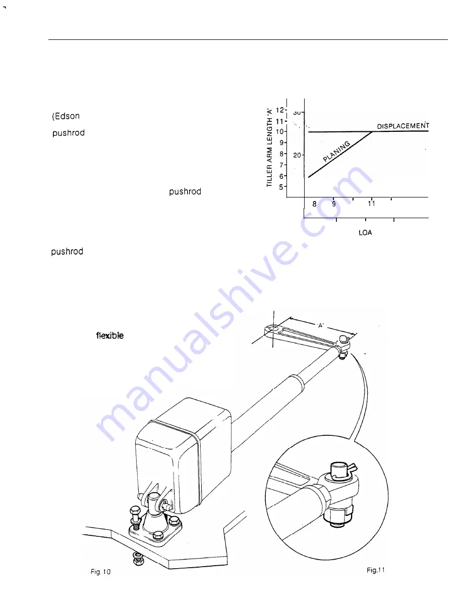
The linear drive unit couples directly to the
rudder stock at the tiller arm length
recommended in Fig. 9. It is usually
preferable to couple the linear drive unit to the
rudder stock via an independent tiller arm
offer a standard fitting). In certain cases,
however, it may be possible to couple the
to the same tiller arm or rudder
quadrant employed by the main steering
linkage. It is important to note that the linear
drive system can exert a thrust of 550lbs. If any
doubt exists about the strength of the existing
tiller arm or rudder quadrant the steering gear
manufacturer must be consulted.
The method of bolting the
ball end
to the tiller arm or rudder quadrant is illustrated
in Fig. 11. It is
vitally important
that the
coupling bolt is fully tightened and the nut
locked by means of the locking tab provided.
The standard ball end fitting will allow for a
maximum angular misalignment between the
and the tiller crank plane of rotation of
up to 5”. Accurate angular alignment is
extremely important and under no
circumstances should the above extreme limits
be exceeded. The body of the drive unit is
mounted by bolting to a substantial frame
member (Fig. 10). As a general rule it is
desirable to ‘over engineer’ the linear drive
unit’s mounting structure to ensure reliability
and maintenance of correct alignment. An
excessively
mount can also severely
impair the steering performance of the
autopilot.
It is important to ensure that the total rudder
movement is limited by the rudder stops built
into the vessel rather than the end stops of the
linear drive output.
LINEAR DRIVE
TILLER ARM LENGTHS
INS
CM
3 0
METRES
I
I
1 0
1 2
1 3
FEET
I
25
3 0
3 5
40
Fig. 9
1
1


