DSP9612RM USER’S GUIDE
0049-0519-000
Page 21
REV.D
LEDs
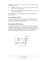
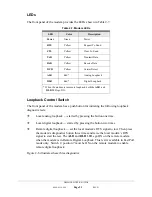
The front panel of the modem provides the LEDs shown in Table 2-7.
Table 2-7. Modem LEDs
LED
Color
Description
Power
Green Power
RTS
Yellow
Request To Send
CTS
Yellow
Clear To Send
TxD
Yellow Transmit
Data
RxD
Yellow Receive
Data
DCD
Yellow Carrier
Detect
ALB
Red* Analog
Loopback
DLB
Red* Digital
Loopback
* When the modem is in remote loopback, both the
ALB
and
DLB
LEDs go ON.
Loopback Control Switch
The front panel of the modem has a push button for initiating the following loopback
diagnostic tests:
Local analog loopback
⎯
started by pressing the button one time.
Local digital loopback
⎯
started by pressing the button two times.
Remote digital loopback
⎯
set the local modem’s RTS signal to low. Then press
the modem’s diagnostics button three times and raise the local modem’s RTS
signal to start the test. The
ALB
and
DLB
LEDs go ON on the remote modem
when the modem is in Remote Digital Loopback. This test is available in Fast Poll
mode only. Switch 2, position 7 must be ON on the remote modem to enable
remote digital loopback.
Figure 2-6 illustrates these three diagnostics.


