PIPe FReeze PROTeCTIOn AnD FLOW MAInTenAnCe
34 of 44
www.tycothermal.com
H55838 2/12
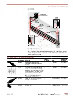
Fig. 17 HTPG power distribution panel
Fig. 18 HTPG power schematic
A
COMMON ALARM
PUSH TO ACKNOWLEDGE
HAND/OFF/AUTO
1
2
3
4
5
6
7
8
9
10
11
12
Main circuit
breaker
Main
contactor
Distribution
panelboard
Fuse holder
C
POWER ON
TB 1
TB 2
AR
R
Ground
bus bar
Selector switch
Alarm relay
(optional)
Terminals
(optional)
Push button for
light testing
Alarm horn (optional)
Alarm option shown above
Door
disconnect
(optional)
N
Ø1
Three-pole main
circuit breaker
Panel
energized
Contactor
coil
C
NC
External controller/
thermostat*
Hand
Auto
Off
Three-pole main
contactor
Ø3
Ø2
Power
connection
Heating cable
One-pole with 30-mA
ground-fault trip
(120/277 Vac)
Two-pole with 30-mA
ground-fault trip
(208/240 Vac)
Alarm
remote
annunciation
(with alarm
option)
Heating
cable
circuit
Heating
cable
circuit
G
End seal
Heating cable shealth, braid or ground
Three-phase, 4 wire supply (Wye)

