The flue system used on this appliance must be provided
by AGA and must be installed in accordance with the
instructions and standards.
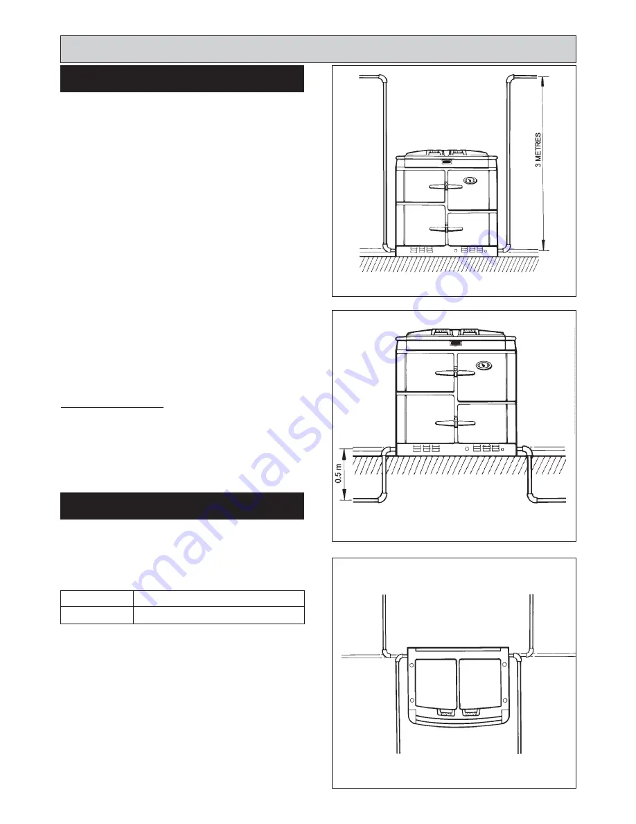
A maximum flue of 5 metres and 5 bends can be used
(including horizontal length on the terminal).
Any upwards vertical runs must be immediate to the
appliance to a maximum of 3 metres. (See Fig. 6)
Downwards vertical runs must be no more than 0.5
metres. (See Fig. 7)
Flue can be positioned to the rear or front of appliance via
1 bend. (See Fig. 8).
Horizontal runs must be as level as possible.
Care must be taken on mounting the terminal and routing
the flue:-
a. Damage to damp proof course
b. Height above ground
c. General terminal locations (See Fig. 9)
Where the flue passes through combustible material a
minimum of 10mm clearance must be maintained around
the flue pipe and insulation sleeve.
General Requirements
The flue pipe must be adequately supported using the
brackets specified.
The flue pipe must be insulated (supplied).
All joints should be sealed using the sealant provided.
The appliance can only be installed in a room which
meets the ventilation regulations in force. But, in any
event the room must have a permanent vent with a
minimum free air area, see below.
IMPORTANT: THE LOUVERED AIR INTAKE AT THE
BOTTOM FRONT OF THIS APPLIANCE MUST BE
KEPT CLEAR OF ANY OBSTRUCTIONS.
9
Site requirements
FLUE SYSTEM
AIR REQUIREMENTS
XTG
35 cm
2
MODEL
MIN. AIR REQUIREMENT
FIG. 6
FIG. 7
FIG. 8
DESN 514115 B
DESN 514116 B
DESN 514114
Содержание XT
Страница 12: ...12 Site Requirements PCB CONNECTIONS FIG 14 EXTERNAL CONNECTIONS FAN CONNECTIONS AT TERMINAL MAINS CONNECTIONS ...
Страница 20: ...20 Wiring Diagram FIG 21 WIRING DIAGRAM APPLIANCE ...
Страница 22: ...22 ...
Страница 23: ...23 ...


