39
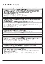
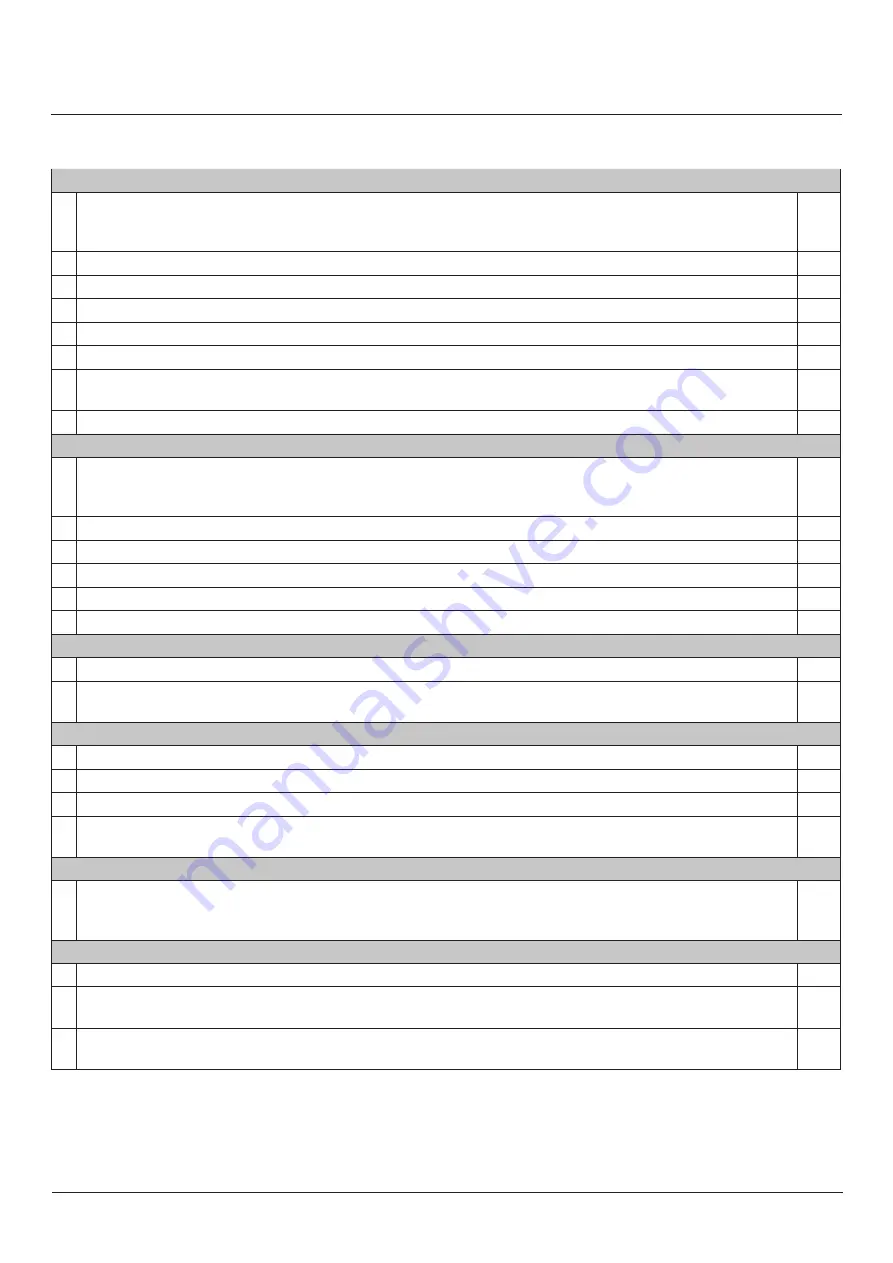
10. Installation Checklist
Flue System
The relevant guidelines must be adhered to for the relevant flue system A, B & C:
A. Use of an Existing Chimney
1.
If connecting to an existing chimney, the appliance should be connected to a 150mm (6”) diameter continuous,
rigid or flexible flue pipe suitable for oil-fired appliances that terminates in excess of 0.6 metres from the nearest
point on the roof measured vertically, and in excess of 2.3 metres measured horizontally.
2. Minimum Flue Height of 4.6 metres (15 feet).
3. Any horizontal flue sections should not exceed 450mm (18”).
4. The chimney serving this appliance should not serve any other appliance.
5. A suitable flue terminal should be fitted at the flue termination point.
6. Closure-clamping plates should be used to seal the top & bottom of the chimney.
7. If the flue passes through a combustible wall, a twin wall insulated connector must be used and come flush to the
external surface of the wall.
8. The flue should be capable of producing a continuous draught of between 0.04” to 0.06” w.g.
B. Use of an External Flue
1.
If using an external flue, the appliance should be connected to a 150mm (6”) diameter rigid insulated flue
pipe suitable for oil-fired appliances that terminates in excess of 0.6 metres from the nearest point on the roof
measured vertically and in excess of 2.3 metres measured horizontally.
2. Minimum Flue Height of 4.6 metres (15 feet).
3. Any horizontal flue sections should not exceed 450mm (18”).
4. The chimney serving this appliance should not serve any other appliance.
5. A suitable flue terminal should be fitted at the flue termination point.
6. The flue should be capable of producing a continuous draught of between 0.04” to 0.06” w.g.
Location
1. The cooker should be installed on a non-combustible material capable of supporting the weight of the unit.
2. The cooker should be positioned so as to maintain a 10mm gap between the cooker and the adjacent kitchen
units.
Plumbing
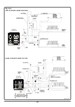
1. A three bar safety valve must be fitted to the primary flow pipe adjacent to the boiler connection on the stove.
2. The cooker must be connected to a fully pumped system using 28mm flow & return supply pipes.
3. A 15mm system by-pass must be fitted not less than 1.5 metres from the cooker.
4. Hot supply to the central heating system should be controlled using a motorised valve with live supply to valve
provided by the relevant connection on the cooker control board.
Ventilation & Combustion Air Requirements
1.
The room in which the appliance is located should have an air vent of adequate size to support correct
combustion when all air-using appliances are working at full capacity (See Ventilation & Combustion Air
Requirement Section for specific details).
Oil Supply
1. The oil supply tank should be fitted with an insolating valve and filter.
2. The stove should be connected to a supply line with a minimum internal diameter of 10mm (3/8”) and must be
fitted with a remote acting fire valve.
3. If a single pipe oil supply system is used, a minimum head of oil of 1 meter must be maintained (see Fuel
Installation Section).

