Internal temperature and time controls are supplied These
provide control of cooking and hot water temperatures.
The cooker is supplied with 2-channel programmer:-
Channel 1 - Marked “COOKER”
Channel 2 - Marked “BOILER”.
A separate switch in conjunction with the hot water
channel gives priority to either the domestic hot water or
the supply of hot water for central heating/DHW (if
external controls are fitted).
It is recommended that independent temperature controls
are provided for comfortable room temperatures, for
economic operation and for control of the domestic hot
water flow to the cylinder.
Consideration should be given to fitting a frost thermostat
which should be set to operate at a temperature of
approximately 4°C.
Consideration must be given when selecting 3 port mid-
position or 2 port zone valves. That they are capable of
handling the heat output of the boiler side, of this range of
appliance.
It is essential that the capacity of the individual valves is
considered to enable the correct size to be chosen.
For this range of appliances, where Honeywell valves are
selected, a guide to selection is as follows:-
Model:
440KB, 22mm (3/4”)
2 or 3 port
460KB, 22mm (3/4”):
2 or 3 port
480KB, 28mm (1”):
2 or 3 port
499KB, 28mm (1”):
2 port only
3 port mid-position valves are inappropriate for selection
with the 499KB model.
The latest publication of Part L of the Building Regulations
states that “separate timing controls should be provided
for space heating and water heating”.
The 400 Series cookers/boilers are fitted with a 2 channel
programmer.
Channel 1 controls the cooking facility.
Channel 2 controls the boiler facility which is space
heating and water heating combined.
To meet the new Building Regulations, the space heating
and water heating functions must have individual timing
controls, therefore we recommend the fitting of an
auxillary programmable room thermostat to control space
heating timings and use channel 2 on the appliance to
control the hot water.
WARNING: POWER TO THE APPLIANCE AND
AUXILLARY CONTROLS i.e. PROGRAMMABLE
ROOM STAT MUST BE VIA THE SAME ISOLATION
SWITCH.
Site requirements
13
HEATING CONTROLS
TIMING CONTROLS
Содержание Heatranger 440
Страница 14: ...Site requirements 440 460 480 499KB EXTERNAL CONTROLS 14 ...
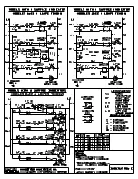
Страница 16: ...16 Site requirements Fig 7 WIRING DIAGRAM 440 460 480 499 KB ...
Страница 19: ...Installation requirements Fig 12 19 ...
Страница 25: ...Sealed System 25 Fig 21 ...
Страница 41: ...41 ...
Страница 42: ...42 ...
Страница 43: ...43 ...


