


16
P/N 42-9470 11/07 Copyright 2007 Mestek, Inc.
Cast iron condensing boiler
Cast iron condensing boiler
— Installation and operation manual
Water piping
(continued)
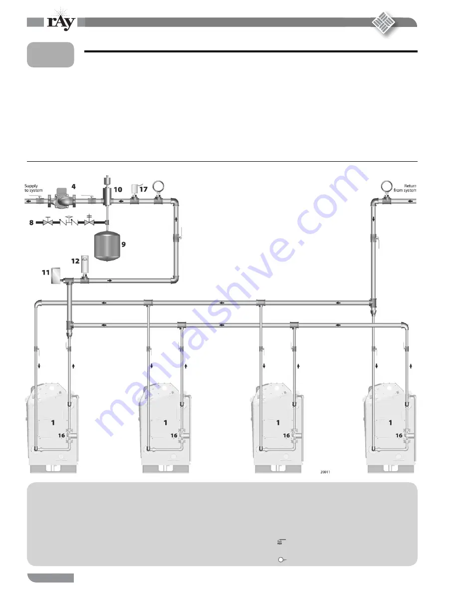
Figure 12
Suggested piping — multiple boilers — parallel-fl ow piping, reverse-return headers
Multiple boilers, parallel fl ow
Sizing and fl ow control
Size the boiler/system circulator to handle the fl ow needs of all zones. If
using variable speed control of the boiler/system circulator, ensure that the
fl ow never drops below the total minimum for all boilers connected. Do
not exceed the maximum fl ow of 50 GPM through any boiler.
DHW operation, when required
When heating system boilers are piped in parallel as in Figure 12, connect
the DHW tank as a zone off of the main header or install boilers dedicated
to the DHW application.
L
EGEND
• • • • • • •
1
200i
boiler
4
Boiler/system
circulator
5
Indirect-fi red DHW tank
(when used)
6
DHW
circulator
8
Cold water fi ll line
9
Expansion tank (shown with diaphragm-type — see
page 12 for piping a closed-type tank) Expansion tank
(shown with diaphragm-type — see page 12 for piping
a closed-type tank)
10
Air separator with automatic air vent (Replace air vent
with piping to the tank fi tt ing on closed-type expansion
systems.)
11
Low water cut-off (when required)
12
Extra high limit (when required)
16
Boiler postpurge circulator (see page 11)
17
Header sensor, required
Isolation valve
Temperature gauge
5