Raven 47800A-V Series Скачать руководство пользователя страница 6


1.3  Changing the Username and Password 

1.


Navigate to the “System” tab on the left panel, click the “Administration” in the drop down, 

and 

it will look like Figure 1-5. 
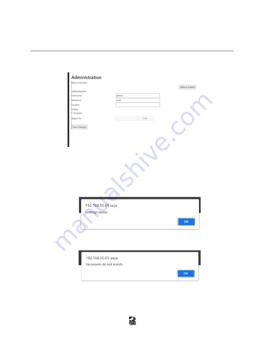


Figure 1-

5: The “Administration” page where the username and password can be changed


2.


Type in the new username, password, and the password again to confirm. Click the “Save 
Changes” button to apply the new credentials.


3.


If the username and password are changed, a pop will appear looking like Figure 1-6. If the 
passwords do not match, it will look like Figure 1-7. 


Figure 1-6: The popup that will appear confirming that the username and password was 

changed.  


Figure 1-7: The popup that will appear when the passwords typed in do does not match.  


Содержание 47800A-V Series

Страница 1: ...Last Updated on February 10th 2022 REV1 PYRA RoIP VoIP Interface User Guide Copyright 2022 RAVEN ELECTRONICS CORPORATION 4655 Longley Lane 106 Reno Nevada 89502...

Страница 2: ...Link Using Pyra Firmware 14 6 2 How to Connect Blades with a FlexGate Using Blade Link 18 7 SIP Channel 20 7 1 How to Associate an Analog Channel with a SIP Account 20 8 Saving the Configuration 23 8...

Страница 3: ...Connecting to the VoIP Interface To configure a Blade that has a VoIP interface in it you will need the power supply sent with the unit as well as a CAT 5 ethernet cable that is connected to your netw...

Страница 4: ...ter that is on your network and go to Properties Internet Protocol Version 4 TCP IPv4 Properties 5 Configure your network adapter with the following parameters Please take note of your current setting...

Страница 5: ...9 Figure 1 4 shows the System Information page that will be brought up once entering the correct username and password Figure 1 4 The System Information page that will pop up once correctly connectin...

Страница 6: ...Type in the new username password and the password again to confirm Click the Save Changes button to apply the new credentials 3 If the username and password are changed a pop will appear looking like...

Страница 7: ...t to the Static IP so you can choose the IP address on your own If you want the DHCP to find an address for you choose Dynamic IP and click the Save Changes button Static IP Address Address The new IP...

Страница 8: ...larity This defines the PTT polarity This is defaulted to normally open when unactive and makes a switch closure when active Unchecking the box will reverse this COR Polarity This defines the COR inpu...

Страница 9: ...re 4 wire Ports Refer to Figure 3 2 and Figure 3 3 for the pinouts for the 153 modules Note the E Lead is COR input and the M Lead is PTT output Figure 3 2 The RJ 45 connector for reference Figure 3 3...

Страница 10: ...panel and it will look like Figure 4 1 Figure 4 1 Conferences web interface 2 Type the name of the bridge being configured 3 Select the ports that need to be bridged as shown in Figure 4 2 Figure 4 2...

Страница 11: ...nel Setup page on the left side panel and it will look like Figure 5 1 Figure 5 1 Channel Setup web interface 2 Type the name of the RTP stream 3 Select RTP Channel under Channel Type and click Create...

Страница 12: ...hen be pointed towards a Multicast IP Address 224 0 0 0 to 239 255 255 255 Multicast TTL The Multicast Time To Live which is number of times the data can pass through a router If the TTL field reaches...

Страница 13: ...the RTP stream with a port 8 Click the name of the RTP channel and one of the ports that the RTP stream will be directed towards as shown in Figure 5 3 Figure 5 3 Selecting the RTP channel and one of...

Страница 14: ...o Port number entered it will automatically be defaulted to Port 8676 Figure 6 1 Example of entering the non server IP address on the 3 Enter the IP Address Port of the non server Blade In our example...

Страница 15: ...e the option for Port 2 as seen in Figure 6 2 9 Click Save Changes 10 Navigate to Blade Setup on the non server webpage 11 Under Blade Link IP and Associated Port the server Blade will be populated Si...

Страница 16: ...s shown in Figure 6 4 The Green LED on the Remote Blade indicates that it is properly linked and the unit is not down Figure 6 4 The Bladelink Status page showing the different Local Blades and Remote...

Страница 17: ...on the sever Blade and PTT output on Port 2 on the non server Blade indicating Blade Link is working Figure 6 6 COR input on Port 2 on the non sever Blade and PTT output on Port 1 on the server Blade...

Страница 18: ...the RTP channel will determine where the blade link signaling will be directed towards 1 Navigate to the FlexGates webpage and log in 2 Click on the Blade Link section on the left side panel to create...

Страница 19: ...e link and clicking the enable button The RTP Channels does not correspond to the individual ports Do not skip unused channels since it can cause problems loading in the settings during FlexGate resta...

Страница 20: ...1234 It is assumed the EXT 1234 under the SIP server is already setup and is ready to connect to this blade The analog channel will be unable to initiate a SIP call but an external device connected t...

Страница 21: ...enabled disabled by the checkbox after it is created Proxy Settings Proxy username The EXT number that is associated with that endpoint under the SIP server Proxy password The password for this endpoi...

Страница 22: ...of the SIP channel and one of the ports you want the SIP account associated with as shown in Figure 7 3 In this example we are associating Port 4 with the 1234 SIP account Figure 7 3 Selecting the SI...

Страница 23: ...ure 8 1 Figure 8 1 Backup Restore web interface 2 Click the Download Settings button The settings will then be downloaded as a json file 3 To upload the json file to get the same configuration on a bl...

Страница 24: ...9 1 Move the jumper to ERASE and MEM Some older modules were made without the jumper pins If you have one that does not have a jumper refer to Section 9 2 How to Reset the VoIP Interface to Have Defau...

Страница 25: ...tore in the drop down 2 Click the Set Defaults button A pop up will appear asking if you want to reset to default settings as shown in Figure 9 2 Click the OK button to continue Figure 9 2 The pop up...

Страница 26: ...e name will appear to the right of the button 3 Click the Upgrade button A message will appear on the same webpage notifying it may take a couple of minutes It will look like Figure 10 2 Figure 10 2 T...

Страница 27: ...e isn t two blades plugged in with the same IP address especially when configuring multiple new blades at once 11 2 Why Am I Getting E M Signaling One Direction but Not the Other Direction when Using...

Страница 28: ...ied the PYRA firmware to a blade that had different older firmware perform a reset to ensure the json file is properly formatted Step 2 If you applied an old json file from an older VoIP firmware to r...

Отзывы: