Commissioning
47
7
7.5
Presetting the mounting height
7.5.1
Safety
General instructions before setting the mounting height
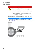
We recommend that you choose the highest coupling point on the tractor to
connect the upper link, particularly for high lifting heights.
The lower coupling points on the machine which are meant for the lower links
of the tractor should be used
only in exceptional circumstances
in late fer-
tilising.
n
DANGER
Risk of being crushed under the falling-down machine
If the upper link halves are accidentally rotated totally apart from
each other, it may happen that the upper link cannot compensate
for the tractive forces of the machine. This may result in the
machine abruptly tilting over backwards or falling down.
This can lead to severe personal injury. Machines can be dam-
aged.
When extending the upper link, always observe the maxi-
mum admissible length specified by the tractor or upper link
manufacturer.
Ensure that nobody is present in the hazard zone of the
machine.
n
WARNING
Risk of injury from rotating spreading discs!
The distribution unit (spreading disc, vanes) may catch and pull-in
body parts or objects. Contact with the distribution unit may injure,
crush or cut off body parts.
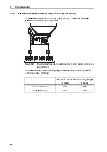
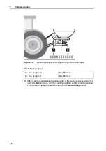
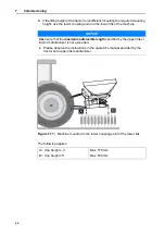
Maximum admissible mounting heights at front (V) and rear
(H) are to be complied with at all times.
Ensure that nobody is present in the hazard zone of the
machine.
Never remove deflectors mounted on the hopper.
NOTICE
Always
use the
upper coupling points
of the machine for normal and late fer-
tilising.
Содержание MDS 14.2
Страница 8: ...Intended use 1 2...
Страница 28: ...Safety 3 22...
Страница 38: ...Technical data 4 32...
Страница 42: ...Axle load calculation 5 36...
Страница 44: ...Transportation without tractor 6 38...
Страница 86: ...Machine settings 8 80...
Страница 96: ...Calibration and discharging residual material 9 90...
Страница 110: ...Important information on spreading 10 104...
Страница 114: ...Faults and possible causes 11 108...
Страница 117: ...Maintenance and service 111 12 1 Flat springs 2 locking bolts Figure 12 1 Locking bolt locked in correctly 2 1...
Страница 146: ......


