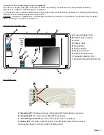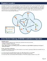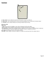
Page 19
4.
To relieve stress on the Ethernet and power cabling, secure it to the cabling tie loop with a tie
5.
If mounting the RC6080 to drywall, install the drywall anchors included in the installation packet
6.
Use four of the provided screws to mount the RC6080, making sure it is flush with the wall
7.
Attach one of the provided screws to the wall through the wall tamper mounting hole
8.
Check that the housing tamper spring is in place and makes contact with the top of the housing
9.
Close the housing
10.
Tighten the housing cover release screw
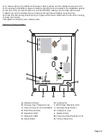
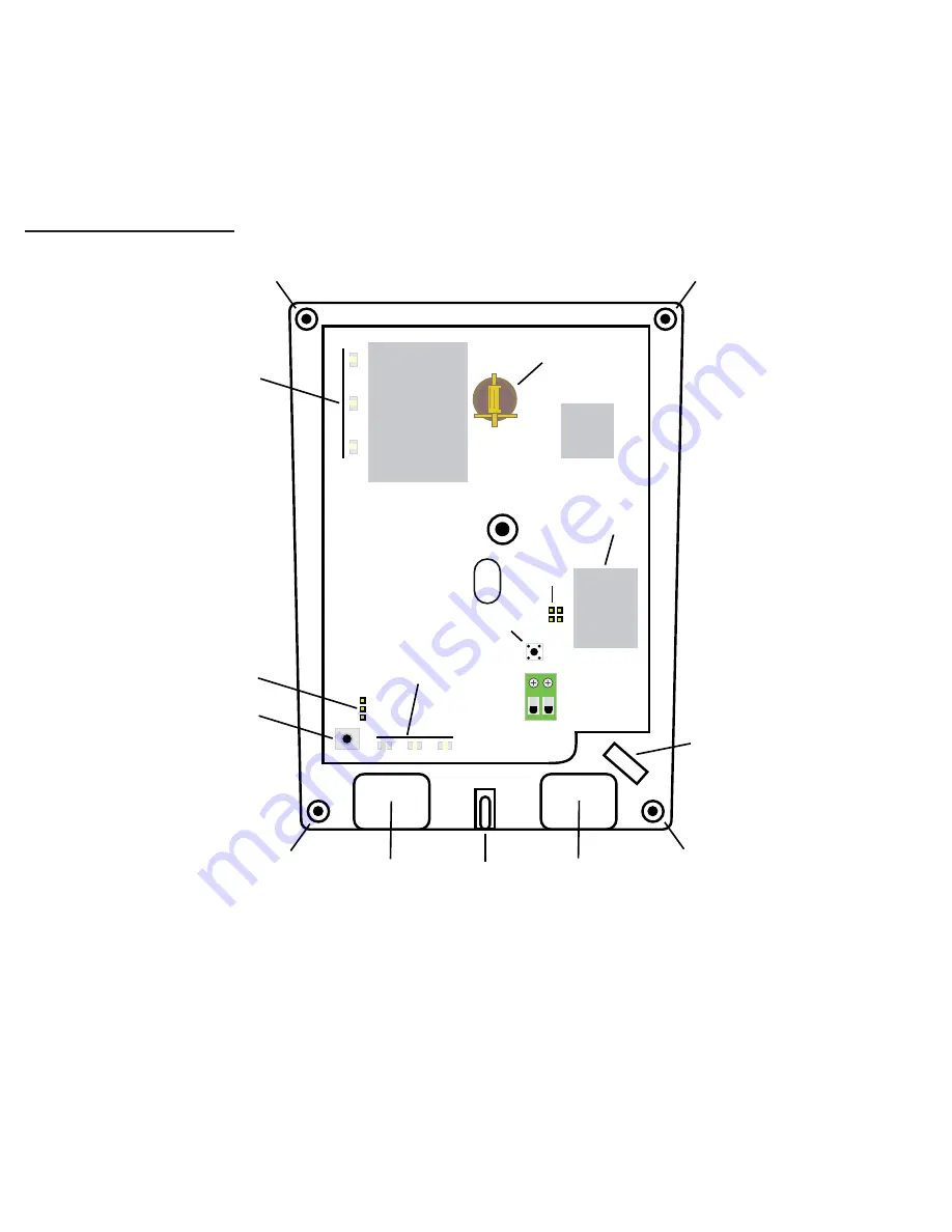
A:
Wall Mount Holes
B:
Housing Cover Release Screw
C:
Power Connection Terminal Block
D:
RJ45 Ethernet Jack
E:
Operation LEDS
F:
Diagnostic LEDS
G:
Reset Button
A
A
A
A
H
B
H
K
G
N
F
J
M
D
I
E
L
STATIC ALARM FAULT
RESET
UART5_RX
GND
UART5_TX
NZ
AU
ETHERNET
POE
+ I
12V
-24V
POWER
AC/DC
LAN
RADIO
POWER
c
Internal Components:
H:
Cabling Port
I:
Wall Tamper Mounting Hold
J:
Housing Tamper Switch
K:
Cabling Tie Loop
L:
Battery Holder
M:
Frequency Band Selection Pins
N:
Factory Reset Pins


