pg. 4
Turn on the Electric
Once the electrical is “live”, you need to program and test the phone and its accessories. Reconnect the
Wago connectors that attach the front plate to the NEMA 4 box. If the phone will be programmed remotely,
secure the front assembly to the back panel, install the top cap, and reinstall the 12 screws to the sides of
the unit. Otherwise, proceed to the directions for Programming the Phone On-Site.
Adjusting the Photocell
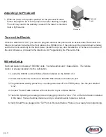
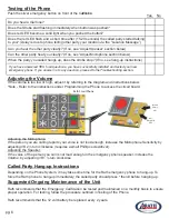
1. Slide the cover to the proper position on the photocell in order
for the blue light to be lit at the proper time (see drawing on right).
The cell may need to be partially covered if the tower is mounted
near a light source
Photocell
Photocell
Cover
www.rathsecurity.com
900 mHz Set-Up
1. Locate the 900mHz unit, with Base Station labeled on the bottom of it.
2. Screw black antenna into back of 900mHz Base Station into antenna port.
3. Plug dedicated analog phone line, or analog extension off of a PBX System, into the port labeled
“Line”.
4. Connect Power Cable included with unit into DC Input on Base Station.
5. Test units by taking an analog phone and plugging it into the “Line” Port on Remote Station installed
in the tower. There should be dial-tone and you should be able to place a call out.
Each call station includes (2) 900mHz units, 1 remote station and 1 base station. The remote
station is already installed into the call station.
6. Verify SmartPhone plugged into “Tel” Port on Remote Station. Phone is now ready for programming.

