

29
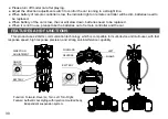
OPERATION GUIDE
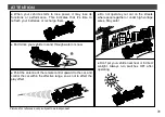
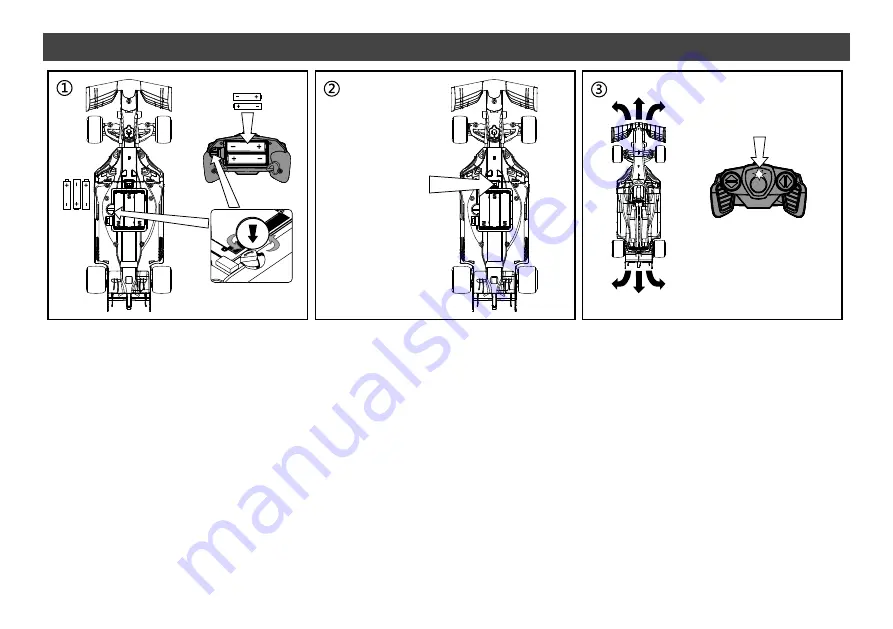
Turn the
switch to “ON”
When indicator light on
remote controller is off,
the code matching is
completed.
Flashing light
of indicator
● Use a coin-like tool to twist the knob switch on battery cover to open or close it. Please refer to Figure
①
.
● Open battery cover, put 3 pieces of 1.5V “AA” batteries according to the correct polarity into the car,
then
close the lid and twist the chassis piece to lock the battery cover.
● Remote controller needs to match code with car before each use. The specific steps are as follows:
● Open battery cover, put 2 pieces of 1.5V “AA” batteries according to the correct polarity into the remote
controller,
then close the lid and twist the chassis piece to lock the battery cover.
Turn switch on R/C car to “ON” position, when indicator light on remote control is flashing, it is in the status
of code matching, when the flashing indicator light on remote control turns off, which means the code is
matched, you can control the car freely. Please refer to Figure
②③
.
● 2.4GHz transmitter is compatible to control several model cars at same time without interference, provided
that the pairing process is orderly done one by one following above steps. Match the code for the first car
according to the steps as mentioned above and keep their power on, then match the code for the second car
in the same way, and so forth for the rest of cars.
Содержание Ferrari SF1000
Страница 1: ...60 5 16 97000 Ferrari SF1000 2 4GHz ...
Страница 12: ...7 11 C29 3 C26 1 Install C29 on 3 2 Install C26 on 3 ...
Страница 13: ...8 Install 6 pieces of 57 on the left and right sides of 3 12 57 57 57 57 57 57 3 ...
Страница 15: ...10 14 C38 C30 C31 4 1 Install C38 on 4 2 Install C30 and C31 on 4 ...
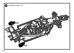
Страница 16: ...11 15 C28 C27 4 Install C27 and C28 on 4 ...
Страница 17: ...12 16 4 B14 B15 Install B14 and B15 on 4 ...
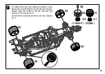
Страница 18: ...17 13 4 B13 59 1 Install 59 on 4 2 Install B13 on 59 ...
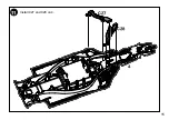
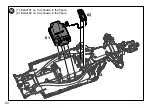
Страница 21: ...20 16 61 62 4 1 Install 61 on 4 as shown in the figure 2 Install 62 on 4 as shown in the figure ...
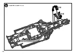
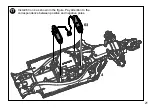
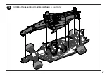
Страница 23: ...17 18 22 60 B16 4 1 Install 60 on 4 as shown in the figure 2 Install B16 on 4 as shown in the figure ...
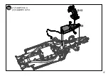
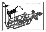
Страница 24: ...19 23 A5 C39 4 1 Install C39 on A5 2 Install A5 on 4 ...
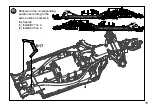
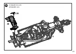
Страница 25: ...20 24 4 B21 B22 Install B21 and B22 on 4 ...
Страница 27: ...22 26 Please press the wire into the gap Plug in respectively while matching by same colours and same shapes ...
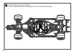
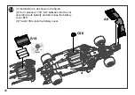
Страница 28: ...17 23 27 Combine the assembled models as shown in the figure ...
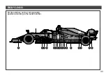
Страница 35: ...34 7 65 55 59 39 35 31 33 43 41 45 63 47 49 13 21 37 ...
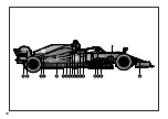
Страница 36: ...35 6 51 55 25 30 29 23 13 54 12 5 4 ...
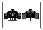
Страница 37: ...36 4 52 22 23 14 15 24 11 28 42 40 44 62 6 10 2 1 5 53 9 26 25 39 43 41 63 3 ...


