background image

2 M

ASTER

C

ONSOLE 

MX4


I

NSTALLATION AND 

O

PERATION 

G

UIDE


Quick Installation and Test 

Chapter 4 specifies a detailed installation procedure. For a quick installation and test of MX

4

, perform the following: 

1.


Plug the power cord into the MX

4

, and turn the power switch to ON. 

2.


Observe the LCD display on the front panel as the MX

4

 goes through a power-on self-test. When the LCD 

displays a circulating

 “Raritan MX48: Base MX48” 

message, the unit is ready. 

3.


Locate user console cable—CCPnnF.  Plug the DB25 connector to a user port on the back panel of the MX

4

 unit. 

4.


Plug a user console-keyboard, monitor, and mouse-into the connectors at the other end of the user cable. 

5.


Login Menu

 will now be displayed on the monitor. The keyboard’s 

<Scroll Lock>

 LED will be blinking.  

6.


Enter 

usera

 as user name, and press 

<Enter>.

 A 

Selection Menu 

will be displayed on the monitor. 

7.


Unwrap a universal cable—CCPnnU. Plug the DB25 connector into a channel on the back panel of the MX

4


unit. 

8.


Plug the other end of the cable to a PC’s keyboard/mouse/VGA ports.  

9.


 Power on the PC. 

10.


The PC channel on the 

Selection Menu 

will turn green. 

11.


Use the keyboard 

<

Ç

and

 <

È

keys to


select the green line, and press 

<Enter>.


12.


You will now be able to operate the PC connected to MX

4

Congratulations! This quick test is complete. 

To go back to the MX

4

 selection menu, press the 

<Scroll Lock>

 key twice rapidly. This activates the on-screen user 

interface. The 

<Scroll Lock> 

LED on the user console keyboard blinks, indicating the on-screen user interface has 

been activated. 


MX

4

 On-Screen User Interface 

The MX

4

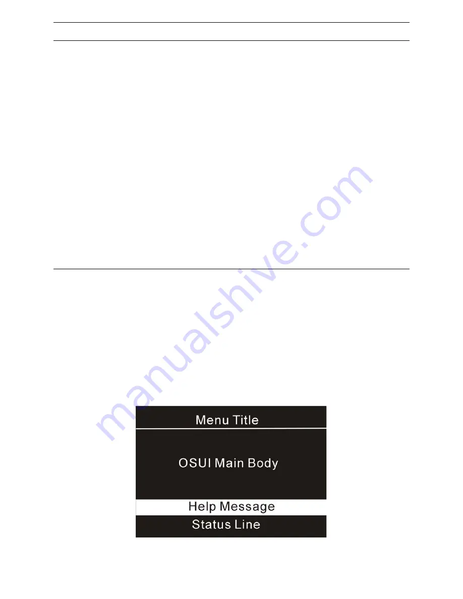
 on-screen user interface (OSUI) consists of a simple hierarchy of menus and screens. Each menu (except 

Login Menu) contains the following sections (Figure 1): 


Title Line 


Menu/Screen Body (for text and fields) 


Help Messages  


Status Line (displays Skip/Scan status, OSUI activator, and P-View indicator if appropriate) 


Function keys F1, F2, F4, and F5 switch between different first-level menus. 


Pressing <F1> while the on-screen user interface is active invokes the Help Screen, which details all options 
available to the user. 


Whenever the on-screen user interface is activated on a user console, that console keyboard’s <Scroll Lock> 
LED indicator blinks.  


Figure 1 OSUI Menu Structure 

Содержание MasterConsole MX48

Страница 1: ...en IJssel The Netherlands Tel 31 10 284 4040 Fax 31 10 284 4049 Hsales europe raritan com Raritan Computer Japan Inc Kuga Building 7F 11 6 Kuramae 4 chome Taitoo ku Tokyo111 0051 Japan Tel 81 3 5833 6...

Страница 2: ...This page intentionally left blank...

Страница 3: ...erence Product names mentioned in this document are trademarks or registered trademarks of their respective companies MasterConsole MX4 MasterConsole II MasterConsole and their respective logos are re...

Страница 4: ......

Страница 5: ...ing a MasterConsole MX 4 Unit for Second Tier Operation 17 Connecting a MasterConsole II C X or S Unit for Second Tier Operation 18 Connecting a MasterConsole P Model for Second Tier Operation 19 Conn...

Страница 6: ...ommunication and Login 39 OverView FAQ s 42 Appendix E Glossary 43 Appendix F Troubleshooting 45 Appendix G Specifications 47 MX4 Models 47 Cable Kits 47 Universal Cable Kits For connecting computer t...

Страница 7: ...ils 21 Figure 22 Device Configuration Menu 1 22 Figure 23 Device Configuration Menu 2 23 Figure 24 Device Configuration Menu 3 23 Figure 25 MX4 Front Panel 26 Figure 26 MX4 Front Panel Buttons 26 Figu...

Страница 8: ...Figure 49 MX4 Basic Configuration 53 Figure 50 MX4 4X64 Configuration 54 Figure 51 MX4 4X256 Matrix Configuration 55...

Страница 9: ......

Страница 10: ......

Страница 11: ...engths of 2 6 5 13 20 and 30 feet Built in dedicated keyboard and mouse emulators for flawless operation Includes Keep alive design to ensure non stop computer operation in case of power loss to the s...

Страница 12: ...ard mouse VGA ports 9 Power on the PC 10 The PC channel on the Selection Menu will turn green 11 Use the keyboard and keys to select the green line and press Enter 12 You will now be able to operate t...

Страница 13: ...4 of the physical MX4 user port to which this user console is currently connected Figure 2 Log in Menu 1 Enter your user name assigned by your administrator If user names have not been assigned the de...

Страница 14: ...Name column lists the computer name The Stat column shows each channel s security class on the left side of the column and the channel specific scan rate in seconds on the right side of the column See...

Страница 15: ...osely matches the characters you type and press Enter 5 When you select a computer you automatically return to normal computer operation at the selected computer If you select a MasterConsole device y...

Страница 16: ...Rate Type a number from 01 to 24 or use the and keys to increment or decrement The default setting is 3 seconds ID Display The ID Display is a small window that shows the computer name and the channel...

Страница 17: ...cess Help get a list of all of the function keys Figure 9 F2 access Selection Menu view the list of channels security levels or scan rates or select a channel F4 access the User Profile or view and ch...

Страница 18: ...8 MASTERCONSOLE MX4 INSTALLATION AND OPERATION GUIDE...

Страница 19: ...aging the system configuration These tools enable the administrator to control access to the MX4 and to all connected computer resources 1 Log in to the system as admin or your user name if you have a...

Страница 20: ...console is idle for that amount of time On Off Use the and keys to toggle On Off Logout Disc Use the and keys to toggle Logout Disc Time Type a number from 01 to 99 or use the and keys to increment o...

Страница 21: ...d the same way as Security Time Out The default setting is On 5 minutes Login Help Mode Use the and keys to select the desired help mode This controls how the help and welcome messages are presented o...

Страница 22: ...he special user name Admin cannot be changed SC The SC column displays the security class of the user Typing A P changes the user s security level typing 0 9 changes the user s security group The defa...

Страница 23: ...ate the access by any user to that channel 3 This menu displays channel information one computer per line MC This is the name of this MX4 same as MX4 ID Ch ID This column displays the physical Channel...

Страница 24: ...14 MASTERCONSOLE MX4 INSTALLATION AND OPERATION GUIDE...

Страница 25: ...16 Complete the following steps for a one tier installation 1 Shut down and power off all computers to be connected to the MX4 2 Install a user console to the MX4 Plug the 25 pin connector of a user...

Страница 26: ...e supplied adapters for AT style computers if needed Figure 17 and Figure 19 Power on the connected computer On the Selection Menu the line displaying the channel to which the new computer has been co...

Страница 27: ...rs Figure 20 Two Tier Configuration Connecting Second Tier MasterConsole s to the Base Unit Power off all MasterConsole units before connecting them to the base MX4 Depending on the model select one o...

Страница 28: ...uously 3 Power off the unit 4 Using a CCPnnU cable plug the keyboard monitor and mouse connectors of the cable to the keyboard monitor and mouse ports on the second tier MasterConsole II OR If you cho...

Страница 29: ...ier Installation detailed in the page 17 Channel Configuration for Two Tier Installation After installing a second tier MasterConsole to a base MX4 you must perform channel configuration from the Admi...

Страница 30: ...nel Configuration option and editing the tier names On MX4 units the tier name can be displayed on the LCD by selecting option 4 on the Administration Menu Set 2nd Tier Names 12 You have now configure...

Страница 31: ...CHAPTER 4 INSTALLING MX4 21 19 Enter Y to save menu or N to re edit Figure 23 Device Configuration Menu 2 Figure 24 Device Configuration Menu 3...

Страница 32: ......

Страница 33: ...denied If the letter levels are equal then the group 2nd position a number determines access Group 0 zero is the universal group if either the user group or the channel group is 0 access is allowed Ot...

Страница 34: ......

Страница 35: ...the front panel control buttons The ESC button B is used for canceling the displayed function and returning the system to the normal state The FUNC button C is used to select the various functions Th...

Страница 36: ...ositions of the display denote the Scan Skip Tier status S K or T or a dot if these options are not active First position S the user port is in AutoScan mode Second character K the user port is in Aut...

Страница 37: ...st be programmed as follows Perform steps 1 3 of Function Selection first To set a second tier user port to connect to a Base MX4 1 Press the or buttons to select the user port number you wish set to...

Страница 38: ...rform steps 1 3 of Function Selection first PW Deactivated T User 1 Ch 2 Figure 32 Disable Front Panel Password 1 When this function is selected the LCD confirms that the password has been deactivated...

Страница 39: ...elected setting or 4 Press ESC to return to the Normal Display and retain the previous setting Select Sync Type User 1 Regular Figure 34 Select Sync Type Certain versions of MX4 hardware have the auto...

Страница 40: ...n of control firmware running on your MX4 unit See Figure 36 Perform steps 1 3 of Function Selection first Ver MXa2 10 Esc to Exit Figure 36 Display Firmware Version 1 Press the or buttons until DSP F...

Страница 41: ...and HEX file 1 DB9 to RJ11 Serial port adapter 1 4 wire Telephone cord Installing MCUpdate 1 Insert the MCUpdate diskette into the floppy drive 2 Run the setup exe program on the diskette and follow...

Страница 42: ...n as an administrator and MANUALLY COPY the current configurations in the attached OSUI menu blanks so that you can re configure the system after the upgrade Firmware version release levels can be che...

Страница 43: ...the Open button Figure 39 File Options Section After the firmware is loaded into memory you can click the button labeled Test Hex File to verify the content This is an optional step Activating the PC...

Страница 44: ...will be displayed Click OK to continue It will take about 2 minutes to complete this step Make sure there are no interruptions of power and avoid performing any activities on the PC or MX4 unit during...

Страница 45: ...APPENDIX C MCUPDATE PROGRAM 35...

Страница 46: ...36 MASTERCONSOLE MX4 INSTALLATION AND OPERATION GUIDE...

Страница 47: ...part number A9FRJ11 1 4 wire telephone cord Installing OverView 1 Insert the OverView diskette into the floppy drive assumed to be A 2 Click the Windows Start button and then click on the Run button...

Страница 48: ...ION GUIDE OverView Operations Running OverView From the Windows Start menu select MC OverView from the Programs menu Select MC OverView to begin the MX4 OverView program Figure 43 Figure 43 OverView S...

Страница 49: ...guration file from MX4 unit into the PC You can now perform maintenance functions Figure 45 Login to Database Real Time MX4 Monitoring OverView allows you to monitor all user activity of in real time...

Страница 50: ...40 MASTERCONSOLE MX4 INSTALLATION AND OPERATION GUIDE Figure 47 Edit User Profile...

Страница 51: ...active version that the MX4 unit operates with Before uploading to the MX4 save a copy in a PC disk file for later reference To update the MX4 configuration click the Send file to MX4 button from the...

Страница 52: ...be a defective serial port on your Windows 95 98 PC After a certain period of OverView operation when I click Send to MX4 the Windows hourglass stays on and will not go away Check the cable connectio...

Страница 53: ...terConsole unit P model MCC MCX or MCS model MX4 model is connected to an MX4 channel Function Selection Screen For accessing front panel control functions Green Mode A field in the User Profile Menu...

Страница 54: ...the security code Selection Menu For selecting a computer or device Set LCD Contrast Screen For adjusting the contrast of the LCD on the MX4 front panel Set Password Screen Enables the administrator...

Страница 55: ...uter Make sure the keyboard is connected firmly into the cable connector and the 25 pin cable is connected to the MX4 Disconnect and reconnect keyboard Replace keyboard MasterConsole allows hot reconn...

Страница 56: ...omputer If the problem is not with the cable or with the specific channel then connect the mouse directly to the computer If the problem persists then the computer s mouse port is out of order Otherwi...

Страница 57: ...2A 115V 230V Auto Sensing 60 Hz 50 Hz 0 3 0 2A Operating Temperature 0 50 C 32 122 F 0 50 C 32 122 F 0 50 C 32 122 F Cable Kits Universal Cable Kits For connecting computer to MX4 PART NO LENGTH CONN...

Страница 58: ...F to HD15 F 2x mini DIN6 F CCP40F 13 3 M DB25 F to HD15 F 2x mini DIN6 F CCP60F 20 6 M DB25 F to HD15 F 2x mini DIN6 F CCP90F 30 9 M DB25 F to HD15 F 2x mini DIN6 F Cascading Cable For connecting MX4...

Страница 59: ...racket for MX416 2U 19 Rack Mount Bracket for MX432 4U APSMAC Converter for Mac Mac ADB and video to PS 2 k b PS 2 mouse and VGA ports APSSUN Converter for Sun Sun k b and video to PS 2 k b PS 2 mouse...

Страница 60: ......

Страница 61: ...MX 4 Basic Configuration 4 Users and Up to 64 Computers Matrix Figure 50 MX 4 4x64 Configuration MX4 4 Users and Up to 256 Computers Matrix Figure 51 MX 4 4x256 Matrix Configuration This configuratio...

Страница 62: ...52 MASTERCONSOLE MX4 INSTALLATION AND OPERATION GUIDE 255 23 0000...

Отзывы: