


49
K5
LIMIT OUT 3
K3_C
K2
LIMIT OUT 4
K4
K5_C
K1
AC HI
F2
1 AMP, 20 MM
K4_C
GROUP A
K2_C
GROUP B
K3
AC LO
TYPICAL of 5 LOADS
K1_C
JP2
1
2
3
4
5
6
7
8
LIMIT OUT 1
LIMIT OUT 5
F1
1 AMP, 20 MM
LIMIT OUT 2
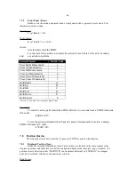
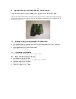
9.4
Relay Limit Switch Connections
Connections to the limit-switch output module are made through an 8 pin removable screw terminal to
connector J1.
Connector J1 Pin-out
JP2-1: Limit Switch output contact 1
Used with Group A
JP2-2: Limit Switch output contact 2
Used with Group A
JP2-3: Limit Switch output contact 3
Used with Group A
JP2-4: Limit Switch output contact 4
Used with Group B
JP2-5: Limit Switch output contact 5
Used with Group B
JP2-6: Reserved
JP2-7: Group A common
JP2-8: Group B common
9.5
Relay Limit Switch Output Cautions:
The maximum current switched by the relay contacts in a group must be limited to 4 amperes. If
the TDD2 supply voltage is switched then arc suppression must be installed to limit noise on the power
supply.
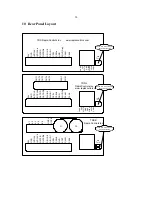
Figure 4 - Example Relay Limit Switch Connections
Содержание TDD2
Страница 8: ...4 2 1 3 Connections for PWM Eavesdrop...