background image

- 10 - 


4.0 REQUIRED TEST EQUIPMENT 


 DC Power Supply (13.8VDC, 10A) 
 RF Wattmeter (25~60 MHz, 50W)  
 Multimeter (Digital) 
 Automatic Modulation Meter 
 Audio Signal Generator 

 Frequency Counter (100 MHz) 
 RF Signal Generator (100 MHz)   
 Automatic Distortion Meter 
 Oscilloscope (50 MHz) 
 Sinad Meter 


4.1 ALIGNMENT PROCEDURES 

This transceiver has been aligned at the factory and does not require any adjustments at installation. 
The required test equipment listed are used for the test setup or alignment shown in Figure 4-1 
Transmitter Test Setup and Figure 4-2 Receiver Test Setup. These test setups are used in part or total 
during the following adjustments and refer to Page 15 for adjustment location. 
 

4.1.1 PLL ALIGNMENT 


ITEM U.U.T. 

SETTING 

ADJUST 

POINT 

MEASUREMENT 

VCO 

Disconnect “short PCB” from TP7, TP8 & TP9.
Set radio to A band, CH 1 AM RX mode. 
Set COARSE/FINE control at 12 o’clock. 
Connect Multimeter to TP2(R116). 


L17 


1.6 VDC 

±

 0.1 


Set radio to 25.615 MHz & 28.305MHz. 
Connect Oscilloscope to TP3(R74). 

 
L18 

 
Maximum Output and 
Balance 


AM Frequency  Set radio to A band, CH 1 AM RX mode. 

Connect Frequency Counter to TP3(R74). 

 
L19 

 
14.9200 MHz + 20Hz


USB Frequency  Set radio to A band, CH 1 USB RX mode. 

Connect Frequency Counter to TP3(R74). 

 
L20 

 
14.9225 MHz + 20Hz


LSB Frequency  Set radio to A band, CH 1 LSB RX mode. 

Connect Frequency Counter to TP3(R74). 

 
L21 

 
14.9175 MHz + 20Hz


TX Frequency  Set radio to A band, CH 1 AM TX mode. 

Connect Frequency Counter to TP3(R74). 

 
VR21 

 
14.9200 MHz + 20Hz


AM OSC 

Set radio to A band, CH 1 AM TX mode. 
Connect Frequency Counter to TP5(D62). 

 
L26 

 
10.6950 MHz + 10Hz


SSB OSC 

Set radio to A band, CH 1 USB TX mode. 
Set radio to A band, CH 1 LSB TX mode. 
Modulation off. 
Short TR31 (Collector & Emitter). 
Connect Frequency Counter to TP6(R102). 

L27 
L28 

10.6925 MHz + 10Hz
10.6975 MHz + 10Hz


4.1.2 TRANSMITTER ALIGNMENT 


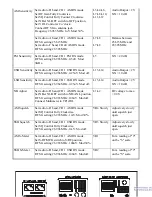
ITEM U.U.T. 

SETTING 

ADJUST 

POINT 

MEASUREMENT 

BIAS Current 

Set radio to A band, CH 1 USB TX mode. 


Содержание SS-3900EGHP

Страница 1: ...rnate Microphones And Installation 7 CHAPTER 3 CIRCUIT DESCRIPTION 3 0 Introduction 8 3 1 PLL Circuit 8 3 2 Receiver Circuit 8 3 3 Transmitter Modulation Circuit 8 3 4 Transmitter Amplifier Circuit 8 CHAPTER 4 ALIGNMENT 4 0 Required Test Equipment 11 4 1 Alignment Procedures 11 4 1 1 PLL Alignment 11 4 1 2 Transmitter Alignment 12 4 1 3 Receiver Alignment 13 CHAPTER 5 MAINTENANCE 5 0 Precautions 1...

Страница 2: ...Output AM FM CW 9W RMS SSB 25W PEP RF Transmit Modes AM FM SSB CW Modulation A3E 16F3 J3E A1A Harmonics And Spurious Emissions 50 dB Carrier Suppression 35 dB Audio Frequency Response 300 to 2500 Hz Antenna Impedance 50 Ohms 1 2 RECEIVER Sensitivity AM 1 0 µV For 10dB S N N FM 0 5 µV For 12dB S N N SSB CW 0 5 µV For 10dB S N N Intermediate Frequency 10 695 MHz AM 1st SSB 455 KHz AM 2nd Image Rejec...

Страница 3: ... receiver 2 SQUELCH CONTROL This knob is used to eliminate background noise being heard through the receiver which can be disturbing when no transmissions are being heard through the receiver To use this feature turn the knob fully counterclockwise and then turn clockwise slowly until the background noise is just eliminated Further clockwise rotation will increase the threshold level which a signa...

Страница 4: ... output power and SWR level 11 RF POWER H M L SWITCH This switch allows the user to select HI MID or LO RF power output 12 NB ANL OFF SWITCH When the switch is place in the NB ANL position the Automatic Noise Limiter ANL in the audio circuits and the RF Noise Blanker NB is also activated The RF Noise Blanker is very effective in eliminating repetitive impulse noise such as ignition interference 13...

Страница 5: ...e black goes to negative and the red goes to positive 3 F C This connector is used for an external frequency counter which indicates the frequency of the selected channel 4 CW KEY The CW key is used for Morse Code operation To operate this mode connect a CW key to this jack and place the MODE switch in the CW position 5 EXTERNAL SPEAKER This jack accepts a 4 8 ohm 5watt external speaker When the e...

Страница 6: ...et the MODE switch to the desired mode 5 Listen to the background noise from the speaker Turn the SQ knob slowly clockwise until the noise just disappears The SQ is now properly adjusted The receiver will remain quiet until a signal is actually received Do not advance the control too far or some of weaker signals will not be heard 6 Set the CHANNEL selector switch to the desired channel 7 Set the ...

Страница 7: ...onductor and its shielded lead comprise two of the leads The third lead is for transmit control and fourth is for receiving control The microphone should provide the functions shown in the schematic below Figure 2 3 4 WIRE MIC CABLE Pin Number Mic Cable Lead 1 Audio Shield 2 Audio Lead 3 Transmit Control 4 Receive Control Figure 2 3 Your Transceiver Microphone Schematic Figure 2 4 Microphone plug ...

Страница 8: ...e receiver depending on the mode of operation The signal is then detected by either the AM FM detector or product detector and then fed to the audio amplifier section of the receiver and finally out to the speaker 3 3 TRANSMITTER MODULATION CIRCUIT i The transmitter modulation circuit modulates the low level RF signal from the PLL exciter circuit with the user s audio voice signal from the microph...

Страница 9: ... 8 ...

Страница 10: ... 9 CHAPTER 4 ALIGNMENT ...

Страница 11: ...E control at 12 o clock Connect Multimeter to TP2 R116 L17 1 6 VDC 0 1 Set radio to 25 615 MHz 28 305MHz Connect Oscilloscope to TP3 R74 L18 Maximum Output and Balance AM Frequency Set radio to A band CH 1 AM RX mode Connect Frequency Counter to TP3 R74 L19 14 9200 MHz 20Hz USB Frequency Set radio to A band CH 1 USB RX mode Connect Frequency Counter to TP3 R74 L20 14 9225 MHz 20Hz LSB Frequency Se...

Страница 12: ...cope to antenna jack VR7 Spurious Emission to minimum AM FM TX Power Set radio to D band CH 1 AM TX mode Modulation off Connect RF Power Meter to antenna jack VR13 9W RF Power Meter Set radio to D band CH 1 AM TX mode Set S RF SWR switch to S RF position Modulation off VR8 For a needle reading in between green and red bar on TX PWR scale CW TX Set radio to D band CH 1 CW TX mode Plug in CW Key Dis...

Страница 13: ...vity Set radio to D band CH 1 LSB RX mode RF SG setting 26 964 MHz 0 25uV Mod off L13 L14 Audio Output 2V S N 10 dB NB Adjust Set radio to D band CH 1 AM RX mode Set NB ANL OFF switch to NB ANL position RF SG setting 26 965 MHz 100uV Mod off Connect Multimeter to TP1 D2 L1 L2 DC voltage to max 2 0V AM Squelch Set radio to D band CH 1 AM RX mode Set SQ Control Fully Clockwise RF SG setting 26 965 M...

Страница 14: ... 13 Figure 4 1 Transmitter test setup Figure 4 2 Receiver test setup SS 3900EGHP MAIN PCB ADJUSTMENT LOCATION ...

Страница 15: ... 14 SS 3900EGHP CHAPTER 5 MAINTENANCE ...

Страница 16: ...nd maintenance Important points to be checked regularly are as follows Check Item Action Whip antenna option If cracked or broken replace it Coaxial cable If sheath is cracked seal with vinyl tape If immersed with water install new coaxial cable Coaxial power plug connections If loosened reconnect If corroded clean contacts Battery connection If corroded clean power terminals Ground terminal If co...

Страница 17: ...ed in the parts list The reference designators are in alphanumeric order 6 1 ORDERING REPLACEMENT PARTS Parts orders should be referred to the Parts Department at Ranger Communications Inc 401 W 35Th ST B NATIONAL CITY CA 91950 7909 Fax 619 426 3788 ROTARY SWITCH PCB EPT360022Z ...

Страница 18: ...13 R316 R317 R318 R319 R321 RCM141024A C F R 1K Ω 1 4W 5 R312 R314 R320 RCM141024B C F R 1K Ω 1 4W 6 CH SW EWRT32000S ROTARY SW GPS 0501 7 J304 EX07N40014 PCB CONN S 10PIN 8 J305 WX01070703 JUMPER WIRE 7x3x7 9 D313 D314 D312 D315 D323 D324 D326 X1 D316 WX01070704 JUMPER WIRE 7x4x7 10 D325 WX01070705 JUMPER WIRE 7x5x7 11 J303 D311 WX01070710 JUMPER WIRE 7x10x7 12 J302 WX01070708 JUMPER WIRE 7x8x7 D...

Страница 19: ... Side PART LIST SS 3900EGHP DISPLAY P C B ITEM REFERENCE NUMBER RANGER PART NUMBER DESCRIPTION 1 EPT360032A DISPLAY PCB 2 DISPLAY PCB EX03N40003 LED DISPLAY RED 3 D309 R T EX01N40004 LED RED GREEN ANT PCB EPT360042Z ...

Страница 20: ... 10 R10 R12 RCY012224Z CHIP F R 2 2K Ω 0 1W 11 R7 RCY011034Z CHIP F R 10K Ω 0 1W 12 C5 RCY011534Z CHIP F R 15K Ω 0 1W 13 C7 CK1059AB1A CHIP C 0 5PF 50WV 14 C6 CK1030AB1A CHIP C 3PF 50WV 15 C3 C4 CK2104AB7R CHIP C 0 1µF 25WV 16 C1 C2 CK1102AB7L CHIP C 0 001µF 50WV 17 Q1 TY2SC2712G TR 2SC2712GR TE85L 18 D3 EDSS00355Y DIODE 1SS355 19 D1 D2 EDHM0198SY DIODE HSM198S 20 D4 EDMA0028TY DIODE MA28T 21 L1 E...

Страница 21: ...CE NUMBER RANGER PART NUMBER DESCRIPTION 1 EPT360050Z DIP PCB 2 C503 C504 CC0501027L C C 0 001µF 50WV 3 C502 CC0504727L C C 0 0047µF 50WV 4 L501 ECCHK16001 CHOKE COIL 5 6µH 5 L502 ECBAD18550 BEAD COIL 3 5x6x1 2 6 MIC PCB EX06N41020 MIC JACK EB 2000B PCB EPT0SSB51J ...

Страница 22: ... EB 2000B P C B ITEM REFERENCE NUMBER RANGER PART NUMBER DESCRIPTION 1 EPT0SSB51J EB 2000B PCB 2 R3 RCY011014Z CHIP F R 100 Ω 0 1W 3 R17 R27 RCY011024Z CHIP F R 1K Ω 0 1W 4 R7 R26 RCY012224Z CHIP F R 2 2K Ω 0 1W 5 R29 R30 RCY014724Z CHIP F R 4 7K Ω 0 1W ...

Страница 23: ... 0 022µF 50WV 23 C22 CK5225AB7R CHIP C 2 2µF 16WV 24 C16 C18 CK1473AB7R CHIP C 0 047µF 50WV 25 C1 C31 CK5475AA7R CHIP C 4 7µF 16WV 26 IC1 YNJR04558M IC NJM4558M 8PIN 27 IC2 YNES56033S IC ES56033S 16PIN 28 Q1 Q3 TY2SC2712G TR 2SC2712GR TE85L 29 Q2 Q5 Q6 TYZRN1403Z TR RN1403 TE85L 30 Q4 FY2SK0208Z FET 2SK208 31 D1 D4 D5 D6 EDSS00355Y DIODE 1SS355 32 D3 EDZD05569Y ZENER DIODE 5 6V 33 C27 CE0164767Z E...

Страница 24: ... 23 SS 3900EGHP MAIN PCB EPT360014C ...

Страница 25: ... 24 Component Side Text Layer SS 3900EGHP MAIN PCB EPT360014C ...

Страница 26: ...U144714Z C F R 470 Ω 1 4W R240 275 126 115 232 RCU145614Z C F R 560 Ω 1 4W R3 44 86 RCU146814Z C F R 680 Ω 1 4W R67 139 140 RCU148214Z C F R 820 Ω 1 4W R33 53 59 91 108 110 120 131 132 130 127 172 209 214 157 236 150 156 140 121 285 18 RCU141024Z C F R 1K Ω 1 4W R82 177 RCU141224Z C F R 1 2K Ω 1 4W R90 190 193 104 227 246 81 RCU141524Z C F R 1 5K Ω 1 4W R17 24 64 68 87 189 155 180 257 RCU142224Z C...

Страница 27: ...01015A C C 100PF 50WV C91 CC0501515A C C 150PF 50WV C162 CC0500301G C C 3PF 50WV C80 CC0501504G C C 15PF 50WV C75 CC0506804G C C 68PF 50WV C160 167 CC0501515G C C 150PF 50WV C82 CC0502715G C C 270PF 50WV C175 CC0503315G C C 330PF 50WV C85 171 209 CC0503915G C C 390PF 50WV C208 COPPER SIDE C170 CC0505615G C C 560PF 50WV C165 CD3005614Z MICA C 560PF 300WV C166 CD3008214Z MICA C 820PF 300WV C161 CC05...

Страница 28: ...L40 ECIFT12014 I F T L42 ECIFT12015 I F T L26 27 ECIFT12016 I F T L17 ECIFT12017 I F T L8 ECIFT12002 I F T L22 ECIFT12258 I F T L39 ECSPG18000 SPRING COIL 0 8x4 2x6 5t L34 ECSPG18087 SPRING COIL 0 8x4x7t L37 ECSPG18001 SPRING COIL 0 8x3 5x7t L51 52 ECSPG18089 SPRING COIL 0 8x6x3 5t L31 ECSPG18075 SPRING COIL 0 8x6x8 5t L33 ECRFZ10045 RF COIL 0 16µH L503 504 ECCHK16000 CHOKE COIL 0 47µH L25 29 30 E...

Страница 29: ...RACKET MT3600050X DC SOCKET HOLDER MT3600061X TOP HOUSING MT3600071X BOTTOM HOUSING MT3600080T D SPRING A MT3600090T D SPRING B MT3600100T D SPRING D MM7878041B HEAT SINK BT148N020T ID PLATE BAA112010D MIC PLATE XZZZ90296A MASK PLATE SW 20mm SWR SW XZZZ90004Z FOAM 14x16x20mm TR43 44 56 XZZZ90358Z INSULATING PLATE 10x14x1 55mm TR43 44 56 XZZZ90003Z INSULATING RING TR51 XZZZ90020Z INSULATING PLATE 1...

Страница 30: ... 29 5 5x10x0 3tmm JW324008CN IN TOOTH WASHER 4x8x0 3tmm LMZZL0013A CHECK PASS LABEL LMZZL0009B SERIAL NO LABEL LZZZ61472Z WARRANTY LABEL ...

Страница 31: ......

Страница 32: ...SS 3900EGHP SCHEMATIC DIAGRAM ...

Страница 33: ...SS 3900EGHP EXPLODE DRAWING ...

Страница 34: ...ΑΤΖΖΖΖ040Α ΧΟΠΨΡΙΓΗΤ 2004 Ρανγερ Χοµµυνιχατιονσ Ινχ ...

Отзывы: