background image

Configuring the R&S TSMA

R&S

®

TSMA

46

Getting Started 1177.5604.02 ─ 10

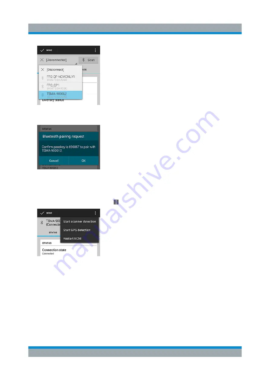
Figure 6-3: Pair NCM

Figure 6-4: Bluetooth pairing request

7. Touch the scanner again in the list to connect to the scanner.

8. Touch the context menu icon   and touch "Start scanner detection".

Figure 6-5: Start scanner detection

The scanner appears in the "Devices" list upon successful detection.

Measurement Modes

Содержание TSMA

Страница 1: ...R S TSMA Autonomous Mobile Network Scanner Getting Started Getting Started Version 10 1177560402 ÛÆ42 ...

Страница 2: ... 164 Email info rohde schwarz com Internet www rohde schwarz com Subject to change Data without tolerance limits is not binding R S is a registered trademark of Rohde Schwarz GmbH Co KG Trade names are trademarks of the owners 1177 5604 02 Version 10 R S TSMA Throughout this manual products from Rohde Schwarz are indicated without the symbol e g R S TSMA is indicated as R S TSMA ...

Страница 3: ...the Instrument 10 4 2 Connecting External Devices 11 4 3 Connecting Power Supply 14 4 3 1 Connecting to a Vehicle DC Power Supply 14 4 3 2 Connecting an AC Power Supply 14 4 3 3 Connecting the R S TSMA BP Battery Pack Unit 14 4 4 Connecting an Additional R S TSME for MIMO Support 20 4 4 1 MIMO 2x2 Upgrade Kit 21 4 4 2 Mounting R S TSME 22 4 5 Connecting Test Mobile Phones 24 4 6 R S TSMA Driver Up...

Страница 4: ... the R S TSMA 37 6 1 1 Start the R S TSMA Web GUI 37 6 1 2 Establish a Remote Desktop Connection 38 6 2 Changing Password of R S TSMA 40 6 3 Measurement Setup 42 6 4 Measurement Modes 43 6 4 1 Remote ViCom Server Mode 43 6 4 2 QualiPoc Mode 44 6 4 3 NESTOR and NESTOR Probe Mode 47 6 4 4 ROMES Mode 49 6 4 5 PC Mode 50 6 4 6 Scanner Only Mode 50 6 5 Power Settings 51 Index 52 ...

Страница 5: ...nd laboratory environments Use the R S TSMA only for its designated purpose Observe the operating conditions and performance limits stated in the data sheet Where do I find safety information Safety information is part of the product documentation It warns you about the potential dangers and gives instructions how to prevent personal injuries or dam age caused by dangerous situations Safety inform...

Страница 6: ...ersion is delivered with the instrument 2 2 User Manuals and Help Contains the description of all instrument modes and functions Includes the con tents of the getting started manual 2 3 Basic Safety Instructions Contains safety instructions operating conditions and further important informa tion The printed document is delivered with the instrument 2 4 Data Sheets and Brochures The data sheet cont...

Страница 7: ...elease notes list new features improvements and known issues of the cur rent firmware version and describe the firmware installation The open source acknowledgment document provides verbatim license texts of the used open source software See www rohde schwarz com firmware tsmx Release Notes and Open Source Acknowledgment OSA ...

Страница 8: ...ogies simultaneously in the 350 MHz to 4400 MHz wireless communications bands It can be combined with an R S TSME to perform LTE MIMO measurements User definable input frequency range from 350 MHz to 4400 MHz RF and signal processing path with a bandwidth of 20 MHz Parallel measurement of all technologies in all bands up to eight technologies simultaneously Integrated Intel PC with Microsoft Windo...

Страница 9: ...strument damage during operation An unsuitable operating site or test setup can cause damage to the instru ment and to connected devices Ensure the following operating conditions before you switch on the instrument The instrument is dry and shows no sign of condensation The instrument is positioned as described in the following sections Signal levels at the input connectors are all within the spec...

Страница 10: ...ote and the accessory lists for the various items Check the instrument for any damage If there is dam age immediately contact the carrier who delivered the instrument Make sure not to discard the box and packing material Packing material Retain the original packing material If the instrument needs to be transpor ted or shipped later you can use the material to protect the control ele ments and con...

Страница 11: ...AN Link interconnection cable 2 Car Adapter cable 3 RF Antenna 4 GPS Antenna 5 WiFi Bluetooth Antennas 4 2 Connecting External Devices The following external devices must be connected before connecting the power supply To select the correct connectors see the following picture Connecting External Devices ...

Страница 12: ...I 9 MINI Display Port 10 LAN Connector CPU 11 DC IN Connector 12 RF IN Connector 13 GPS Antenna Connector 14 Antenna 1 Connector Bluetooth WLAN MIMO 15 Antenna 2 Connector WLAN 16 RESTORE 1 Connect the SCAN ports of scanner and PC unit of the R S TSMA Figure 4 3 Connection between scanner unit and internal PC unit 1 SCAN Link connector CPU port 2 SCAN Link connector Scanner Port 3 SCAN Link interc...

Страница 13: ...r MINI Display port if you want to use local operation optional If necessary following display port adapters can be used Display Port Adapter to DVI HDMI R S TSPC DPDH R S No 3592 4060 02 Figure 4 4 Display Port Adapter to DVI HDMI Display Port Adapter to VGA R S TSPC DPVG R S No 3592 4076 02 Display Port Adapter to VGA 6 Connect a LAN cable to the LAN port if you want to use the R S TSMA via Remo...

Страница 14: ...upply only DC based lab networks are not allowed to be used for power supply 4 3 2 Connecting an AC Power Supply To operate the R S TSMA with an AC power supply connect the DC IN connec tor with the AC power supply R S TSMA Z1 R S No 1523 8450 02 Use only the R S TSMA Z1 R S No 1523 8450 02 as AC power supply Figure 4 5 TSMA Z1 AC Power Supply 4 3 3 Connecting the R S TSMA BP Battery Pack Unit Alt...

Страница 15: ...Make sure that the batteries are inserted in the correct orientation Figure 4 6 R S TSMA Battery Orientation 1 Battery insert orientation 2 Attach the R S TSMA base unit with the bottom side see Figure 4 8 on top of the R S TSMA BP see Figure 4 7 Figure 4 7 R S TSMA BP 1 Connectors for R S TSMA base unit Connecting Power Supply ...

Страница 16: ...SMA BP 3 Move the R S TSMA base unit to the front side 2 until the connectors are locked Figure 4 9 Connected R S TSMA Base Unit and R S TSMA BP 1 Vertical attachment of R S TSMA base unit bottom with R S TSMA BP top 2 Move T S TSMA base unit to the front side 4 Lock the interconnection using the lock 3 Connecting Power Supply ...

Страница 17: ...ection of R S TSMA with R S TSMA 1 R S TSMA Base Unit 2 R S TSMA 3 Lock front side 5 Via the cable 3 you have to connect the DC IN connector on the R S TSMA 1 with the TSMA connector 7 pins on the R S TSMA BP 2 Figure 4 11 Cabling of R S TSMA with R S TSMA Connecting Power Supply ...

Страница 18: ...fter connecting the R S TSMA BP Battery Pack Unit including charged batteries or connected to an external DC power supply with the R S TSMA depends on the system settings on the R S TSMA The R S TSMA BP Battery Pack Unit can be connected with an external power supply The following steps must be performed 1 DC powered from a vehicle supply see Figure 4 14 Connect the DC IN connector 4 of the R S TS...

Страница 19: ...xternal DC supply and the batteries inside the R S TSMA BP are charged If the external DC supply is not available the R S TSMA is powered from the batteries Figure 4 14 Connecting the R S TSMA with an AC power supply 1 DC IN connector R S TSMA Base Unit 2 TSMA connector R S TSMA BP Battery Pack Unit 3 DC power interconnection cable R S TSMA Base Unit R S TSMA BP Battery Pack Unit 4 DC IN connector...

Страница 20: ...tension the following is needed MIMO 2x2 Upgrade Kit R S No 15246439 02 R S TSMA driver update software TSMA_DriverUpdate_1 00 exe which can be downloaded from the Rohde Schwarz web site The R S TSMA driver update must be performed before connecting the additional R S TSME Figure 4 15 R S TSMA with R S TSMA BP battery pack unit and mounted R S TSME front side view Connecting an Additional R S TSME...

Страница 21: ...ect the devices The following items are included in the MIMO 2x2 Upgrade Kit R S TSPC U2L USB 3 0 to LAN Adapter 3593 8430 02 DC Cable TSMA BP TSME to connect R S TSMA BP with R S TSME 1523 8480 00 SYNC Cable 2 TSME 1522 6577 00 RJ45 Patch cable shielded CAT5E 15 cm 5016 1890 00 Holder TSMA PB TSME 1523 8415 00 VS 7985 ISR M3X5 A4 PA 3565 7210 009 VS 7985 ISR M2 5X5 A4 PA 1148 2617 00 Installation...

Страница 22: ... Figure 4 17 Some items of the upgrade kit 1 SYNC cable for TSME 2 Holders 3 Turnlock fasteners 4 4 2 Mounting R S TSME 1 Screw the delivered holders to both devices Note the differences when screwing the holders Connecting an Additional R S TSME for MIMO Support ...

Страница 23: ... screwed on the devices 2 Fasten the R S TSME onto the R S TSMA attaching the R S TSME as shown in the following figure Figure 4 19 Mounting R S TSME on R S TSMA 3 Connect devices using the cables including the MIMO 2x2 Upgrade Kit Connecting an Additional R S TSME for MIMO Support ...

Страница 24: ...of the combination TSMA BP TSME to R S TSPC 2UL USB 3 0 to LAN Adapter 4 SCAN Link interconnection cable not included in MIMO 2x2 Upgrade Kit 5 Connection TSME AUX port to TSMA AUX port SYNC Cable 2 TSME 4 5 Connecting Test Mobile Phones To use the R S TSMA with test mobile phones the following steps must be per formed 1 Install the driver package for the test mobile phones see Chapter 4 6 R S TSM...

Страница 25: ... a Samsung test mobile phone is connected to the R S TSMA The up to date instrument driver is available for download under https www rohde schwarz com driver tsma 4 6 1 Installation MIMO Extension For the installation of the driver update package R S TSMA ThinkPad USB LAN Setup 1 00 the R S TSPC U2L USB 3 0 to LAN Adapter 3593 8430 02 must be connec ted to the R S TSMA 1 Connect the LAN adapter to...

Страница 26: ...26 Getting Started 1177 5604 02 10 Figure 4 21 R S Software Distributor opening page 3 Select Local Installation and click Next The opened page shows the contents of the R S TSMA Driver Update Pack age 1 00 R S TSMA Driver Update ...

Страница 27: ... click Install 5 Close the installation The tool installs the required package and assigns the 192 168 2 1 IPv4 address to Ethernet adapter automatically Figure 4 23 Installed package Make sure that the IPv4 address 192 168 2 1 is not used by any other LAN adapter The R S TSME IP address has to be set to 192 168 2 x to support the R S TSMA MIMO measurements R S TSMA Driver Update ...

Страница 28: ...ers Install the mobile device drivers before connecting a test mobile phone 1 Download the TSMA_DriverUpdate_1 00 exe file from the Rohde Schwarz web site and run it The R S Software Distribution welcome to install page opens Figure 4 24 R S Software Distributor opening page 2 Select Local Installation and click Next The opened page shows the contents of the R S TSMA Driver Update Pack age 1 00 R ...

Страница 29: ...MA Driver Update Package 3 Select R S TSMA Samsung Android USB Setup 1 00 and R S TSMA Qualcomm Driver Setup 1 00 and click Install 4 Close the installation The tool installs the required packages For more see ROMES UE Application pdf included in the delivered R S ROMES DVD R S TSMA Driver Update ...

Страница 30: ...MA does not provide any connectors or control ele ments for operation Figure 5 1 R S TSMA Front Panel 5 2 Rear Panel The following figure provides an overview of the control elements and the connec tors on the rear panel of the instrument Figure 5 2 R S TSMA Rear Panel 1 POWER ON OFF 2 STATUS LEDs 3 AUX Connector Rear Panel ...

Страница 31: ...via the DC IN connector STATUS LEDs The three status LEDs STATE SCAN PWR indicate the operating status of the R S TSMA For a detailed description see Chapter 5 3 Status LEDs on page 34 AUX Connector The AUX connector can be used to synchronize the R S TSMA with the external 10 MHz reference frequency output of a signal generator or to synchronize multi ple R S TSMA TSME in a MIMO setup the Sync ca...

Страница 32: ...lay the status of the scan link intercon nection For a detailed description see Chapter 5 3 2 SCAN LINK on page 36 USB 2 0 2x The two USB 2 0 ports can be used for connecting external devices as keyboard mouse or other devices USB 3 0 2x The two USB 3 0 ports can be used for connecting external storage devices data sticks and test mobile phones Mini HDMI Port The MINI HDMI port can be used for con...

Страница 33: ... on the left side of the connector LED 2 green activity status is on the right DC IN Connector The DC IN connector is used to supply the R S TSMA with DC power A wide DC input range 10 to 18 V max 4 A is supported Use only cable type with R S No 1523 7948 00 included in delivery pack age RF IN Connector The RF IN connector is the RF input of the R S TSMA The multi band RF pad dle antenna 700 MHz t...

Страница 34: ...this SMA connector Antenna Connector 2 WLAN The port with the label 2 is the WLAN antenna port Connect one of the accessory WLAN Bluetooth antennas to this SMA connector RESTORE With the RESTORE button it is possible to bring the R S TSMA back to factory default Loss of user data after RESTORE Executing restore brings the R S TSMA irreversible back to the condition of delivery or any other later s...

Страница 35: ...f amber cont Idle WLAN On Device powered idle state WLAN AP is on blue off green cont Idle WLAN Off Device powered idle state WLAN AP is off blue green LED controlled by software appli cation Ready Scanner module connected no measurement blue green flashing rapidly LED controlled by software appli cation Busy Active scanner measurement running blue amber 2 sec red 2 sec off green blinking 1Hz Powe...

Страница 36: ... used for these applications 5 3 2 SCAN LINK Table 5 1 SCAN Link LED1 link states and their meaning LED state Description off No link yellow blinking Identify scanner module TSME Device Manager test synchronous with SCAN LED and SCAN Link LED2 yellow Link established Table 5 2 SCAN Link LED2 activity states and their meaning LED state Description off No data green blinking Identify scanner module ...

Страница 37: ...6 1 2 Establish a Remote Desktop Connection on page 38 6 1 1 Start the R S TSMA Web GUI To start the R S TSMA Web GUI via a remote PC three possible ways are avail able WLAN 1 Via a tablet or smartphone you have to establish a WLAN connection to R S TSMA WLAN access point a Search for a TSMA WLAN network The WLAN access point on the R S TSMA is started automatically by default during the boot proc...

Страница 38: ...mber of this specific R S TSMA Local access from the R S TSMA and Windows Explorer Open Internet Explorer using mouse keyboard and monitor The R S TSMA Web GUI opens automatically If not type the following http localhost 6 1 2 Establish a Remote Desktop Connection To establish a remote desktop connection the following steps must be performed 1 A WLAN LAN connection between the R S TSMA and the rem...

Страница 39: ...Started 1177 5604 02 10 User name instrument Note For access via IP address use the following IP addresses WLAN 192 168 1 10 LAN IP address is assigned by the host PC 5 Click Connect 6 Enter the password 894129 and click OK Accessing the R S TSMA ...

Страница 40: ... of R S TSMA To change the default password default PW 894129 of R S TSMA proceed as follows After changing the password additional steps has to be performed for Autologin Change Password 1 On R S TSMA open the Control Panel 2 Navigate to User Accounts Change account type 3 In the following window double click the account instrument to edit the set tings Changing Password of R S TSMA ...

Страница 41: ...s 1 and click Change password 2 Enable Autologin After changing the password change the password also in Autologin settings To change the Autologin settings proceed as follows 1 Open the Registry Editor 2 In the Registry Editor navigate to HKEY_LOCAL_MACHINE SOFTWARE Microsoft Windows NT Changing Password of R S TSMA ...

Страница 42: ...rd 4 Click OK The changes are accepted After powering the R S TSMA auto matically login 6 3 Measurement Setup The measurement setup procedure is performed in the following steps 1 Start the R S TSMA Web GUI see Chapter 6 1 1 Start the R S TSMA Web GUI on page 37 2 Check the prerequisites of the desired measurement mode see Chapter 6 4 Measurement Modes on page 43 and adjust your device according t...

Страница 43: ...nt see Chapter 6 3 Measurement Setup on page 42 The R S Remote ViCom Server is installed on all the R S TSMAs The other software applications that is the R S NESTOR R S ROMES and QualiPoc are installed only if ordered 6 4 1 Remote ViCom Server Mode The connection between the Remote Vicom server on the R S TSMA and the cli ent application Remote ViCom client on the handheld device can be realized v...

Страница 44: ...ments for operating the rViCom Sample App have to be fulfilled see R S TSMA User Manual 1 Activate the rViCom Server mode see Chapter 6 3 Measurement Setup on page 42 2 Start one of the following applications a Start the OEM rViCom client application on the mobile device b Start the rViCom Sample App on the mobile device For more details refer to R S TSMA User Manual 6 4 2 QualiPoc Mode To use the...

Страница 45: ...nager 4 Touch the plus sign at the top of the screen and touch NCM Figure 6 1 Add NCM Note The NCM provides the Bluetooth connection to the scanner 5 Touch Scan at the top of the screen and wait until the scanning process stops Figure 6 2 Scan for NCM 6 Touch Disconnected touch the TSMA scanner in the list for example TSMA 900012 and then touch to accept the pairing request Measurement Modes ...

Страница 46: ...NCM Figure 6 4 Bluetooth pairing request 7 Touch the scanner again in the list to connect to the scanner 8 Touch the context menu icon and touch Start scanner detection Figure 6 5 Start scanner detection The scanner appears in the Devices list upon successful detection Measurement Modes ...

Страница 47: ...e R S TSMA Configuration and control of the measurement is done on a remote PC To use the R S TSMA in NESTOR mode the following steps must be per formed Prerequisites R S TSMA NESTOR software package must be installed on the R S TSMA The software package is pre installed at delivery when the R S TSMA is ordered with NESTOR TSMA Option R S No 1522 8870 03 Note The R S NESTOR software installation c...

Страница 48: ...peration Mode NESTOR work space select box Measurement To use the NESTOR or NESTOR Probe mode the following steps must be performed 1 In the Web GUI change the Mode of Operation to NESTOR or NESTOR Probe see Chapter 6 3 Measurement Setup on page 42 2 According to the selected mode following additional settings are required a NESTOR mode Select a workspace b NESTOR Probe mode Client and server dete...

Страница 49: ...via the R S TSMA Web GUI To use the R S TSMA with R S ROMES the following steps must be performed Prerequisites R S TSMA ROMES software package TSMA ROMES setup version exe has to be installed on the R S TSMA see R S TSMA User Manual A ROMES license dongle must be connected to a USB port of the R S TSMA Import of ROMES Workspace File Importing of the R S ROMES workspace file is an additional requi...

Страница 50: ...s feature the ROMES option ROMES4RCO is required 3 Click Submit to save your selection For more details about the R S ROMES configuration and usage refer to the user documentation for R S ROMES 6 4 5 PC Mode The PC Mode is used for software update of the R S TSMA 6 4 6 Scanner Only Mode In the scanner only mode only the scanner unit of the R S TSMA is active the PC unit is in stand by mode In this...

Страница 51: ...ings The power settings for an R S TSMA can be modified according to following rules With the setting Auto Power On the R S TSMA starts automatically when a DC power supply is connected With the setting Remember Last State the R S TSMA uses the last state before the R S TSMA was powered off Additionally the setting Auto Power Off can be activated In this case the R S TSMA is powered off if a DC po...

Страница 52: ...7 5604 02 10 Index B Brochures 6 D Data sheets 6 G Getting started 6 H HDMI Port 32 Help 6 L LED LAN Connector 33 Status 31 M MINI Display Port 32 O Open source acknowledgment OSA 7 R Release notes 7 S Safety instructions 6 U User manual 6 ...

Отзывы: