Concepts and features
R&S
®
ZNA
223
User Manual 1178.6462.02 ─ 20
Table 4-18: Properties of frequency windows
Window
Side lobe sup-
pression
Relative impulse
width
Best for...
No Profiling (Rect-
angle)
13 dB
1
–
Low First Side lobe
(Hamming)
43 dB
1.4
Response resolution: separation of
closely spaced responses with compara-
ble amplitude
Normal Profile
(Hann)
32 dB
1.6
Good compromise between pulse width
and side lobe suppression
Steep Falloff (Boh-
man)
46 dB
1.9
Dynamic range: separation of distant
responses with different amplitude
Arbitrary Side lobes
(Dolph-Chebychev)
User defined
between 10 dB and
120 dB
1.2 (at 32 dB side
lobe suppression)
Adjustment to individual needs; tradeoff
between side lobe suppression and
impulse width
4.7.2.4
Harmonic grid
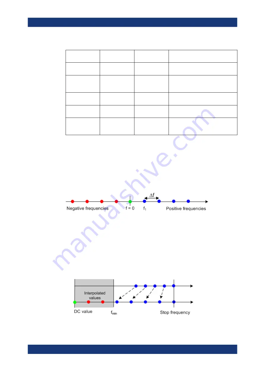
A harmonic grid is formed by a set of equidistant frequency points f
i
(i = 1...n) with
spacing Δf and the additional condition that f
1
= Δf. In other words, all frequencies f
i
are
set to harmonics of the start frequency f
1
.
If a harmonic grid, including the DC value (f = 0), is mirrored to the negative frequency
range, the result is again an equidistant grid.
The point symmetry with respect to the DC value makes harmonic grids suitable for
lowpass time domain transformations.
Visualization of the harmonic grid algorithms
The R&S
ZNA provides three different algorithms for harmonic grid calculation. The
three harmonic grids have the following characteristics:
●
Keep "Stop Frequency and Number of Points" means that the stop frequency and
the number of sweep points is maintained. The sweep points are redistributed
across the range between the minimum frequency of the analyzer and the stop fre-
quency; the step width can be increased.
●
Keep "Frequency Gap and Number of Points" means that the number of sweep
points and their relative spacing is maintained. If the start frequency of the sweep
Optional extensions and accessories


