Page
6
of
15
LP0298BK
R&G Racing
Unit 1, She
lley’s
Lane, East Worldham, Alton, Hampshire, GU34 3AQ
Tel: +44 (0)1420 89007 Fax: +44 (0)1420 87301
FITTING INSTRUCTIONS
•
If fitted, remove the OEM pillion grab rail, then remove the 3x bolts securing the RHS upper
panel using a 5mm Allen tool, as shown in picture 1, then gently pull away to remove. Using a
6mm Allen tool, remove the rider
’s footrest
as shown in picture 2, then remove the lower panel
using a Phillips-head screwdriver, as shown in picture 3.
•
Disconnect the connector shown in picture 4, then unclip the wiring loom from the RHS of the
swingarm.
•
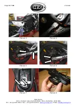
Using a 5mm Allen tool, remove the 2x bolts on either side securing the rear fender to the
swingarm, as shown in picture 5. Using a 10mm socket and wrench, remove the 2x bolts on
either side of the swingarm securing the OEM tail bracket as shown in picture 6, then gently
remove the whole assembly from the bike.
•
Use the key to remove the seat, then connect the long wiring adaptor
(item 9)
to the
connector earlier disconnected. Route through the subframe so the bullet connectors are in the
position shown in picture 7, then using a Phillips-head screwdriver, remove the 2x bolts shown
in picture 7, to loosen the undertray.
•
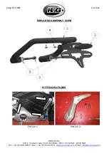
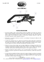
Fit the new taillight
(item 2)
to the new tail bracket
(item 1)
as shown in picture 8, then
secure using the included 2x M4 bolts, using a 2.5mm Allen tool.
•
If using the original indicators
, remove from the OEM tail bracket, then secure to the R&G
tail bracket using a 14mm spanner. Fit the wiring covers
(item 8)
to cover the securing nuts,
then fit a wiring extension
(item 10)
to each indicator to give the correct wiring length.
•
If fitting R&G mini-indicators
(R&G mini-indicator product code RG374 for LED type, or
RG372 for Aero Style LED type), secure to the R&G tail bracket using a 13mm spanner, then fit
the wiring covers
(item 8)
to cover the securing nuts. Fit a wiring extension
(item 10)
to each
indicator to give the correct wiring length.
•
Neatly wrap the light and indicator wires with the included thinner heat shrink
(item 6)
, then
group the wires together and wrap with the wider heat shrink
(item 7)
to create a loom.
•
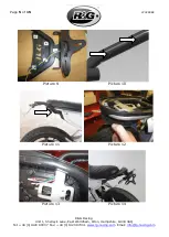
Tidy and secure the wiring to the tail bracket using the included cable clips
(item 12)
, as
outlined in picture 9, ensuring the loom runs down the RHS of the bracket. Then, use the cable
ties
(item 11)
to secure the loom to the bracket, threading through the drilled holes on the
RHS of the bracket
’
s tubular frame, as shown in picture 10.
•
Offer the new tail bracket assembly up to the grab rail mounts, then using a 6mm Allen tool,
secure with the included M8 bolts
(item 3)
and washers
(item 5)
, as shown on picture 10. Fit
a cap
(item 14)
to the head of each bolt.
•
Gently pull the undertray down as shown in picture 11, then pull the end of the loom through
the undertray cut-out as shown in picture 13.
•
Connect the loom bullet connectors to the previously fitted long wiring adaptor in the following
order:
ORANGE
–
LHS IND (YELLOW OR RED)
BLUE
–
RHS IND (YELLOW OR RED)
GREEN
–
BRAKE LIGHT SW (
BLUE
)
BROWN
–
REAR LIGHT/LICENSE PLATE LIGHT + (YELLOW)
GROUPED BLACK
–
ALL NEGATIVE WIRES (BLACK
(CAN BE GREEN FROM BRAKE LIGHT
)


