ICI16• 9
NOTE TO NEWCOMERS: If you are a first time kit builder we hope you find
this manual easier to understand than you may have expected. Each part in
the kit is checked off as you go, while a detailed description of each part is
given. If you follow each step in the manual in order, and practice good
soldering and kit building skills, the kit is next to fail-safe. If a problem does
occur the manual will lead you through step by step in the troubleshooting
guide until you find the problem and are able to correct it.
Although we know that you are anxious to complete the assembly of your
infrared controller kit it is best to follow the step-by-step instructions in this
manual. Try to avoid the urge to jump ahead installing components.
Since you may appreciate some warm-up soldering practice as well as a
chance to put some landmarks on the PC board, we’ll first install some of the
larger components. This will also help us to get acquainted with the up-down,
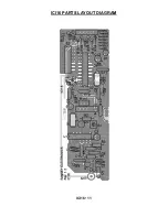
left-right orientation of the circuit board. Have a look at the parts layout
diagram to help with your assembly.
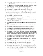
Use the boxes to check off your progress.
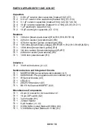
Check all received parts against the parts list. The parts list describes the
various markings that may be found on the kit parts. Carefully sort the parts
into small piles to aid in finding the correct part at the required time.
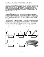
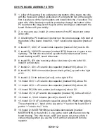
We will begin by installing the input and output connectors on the rear side of
the circuit board. These will act as our landmark components and make the
orientation of the rest of the parts a bit easier.
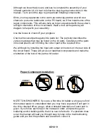
Proper Component Installation:
Содержание ICI16
Страница 11: ...ICI16 11 ICI16 PARTS LAYOUT DIAGRAM ...
Страница 20: ...ICI16 20 These pages were intentionally left blank to provide plenty of room for notes ...
Страница 21: ...ICI16 21 ...
Страница 22: ...ICI16 22 ...


