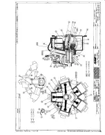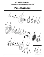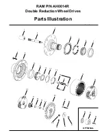
STEP 11
Secure bearing nut (14) by bending a lock washer (13) tab into one of four bearing nut slots. If no tab
aligns with a slot, the nut may be tightened until one of the slots aligns with a lock washer tab.
STEP 12
Assemble a washer (16), spring (17), a second washer (16), and a retaining ring (15) in the middle
grooves of input shaft (2). Install a second retaining ring (15) in groove near small end of input shaft (2).
STEP 13
Assemble the splined end of the input shaft (2) down into spindle (3).
STEP 14
Assemble the secondary carrier assembly (19) to spindle (3) at splines.
STEP 15
Clean mating surfaces and apply a bead of silicone sealant to face of hub (9) that mates with ring gear
(18). See instructions on sealant package. Assemble ring gear (18) to hub (9) being careful to align bolt
holes.
STEP 16
Assemble the primary carrier assembly (20) into the ring gear (18). It will be necessary to rotate carrier
to align secondary sun gear {part of primary carrier assembly (20)} with planet gear teeth in secondary
carrier assembly (19). Assemble primary sun gear (21) over input shaft (2). Rotate primary sun gear
(21) to align input shaft (2) to gear splines and gear teeth in primary carrier assembly (20).
STEP 17
Lubricate “O” ring (24) and assemble in groove inside cover hole, push disengage plunger (23) into
cover (25) with pointed end facing inside of unit.
STEP 18
Assemble the thrust washer (22) with tangs engaged with cover (25).
NOTE:
A small amount of grease
applied to the back side of thrust washer (22) will hold washer in place. Apply a bead of silicone sealant
to end of face of ring gear (18). Assemble cover (25) aligning holes of cover and ring gear. Assemble
the twentyfour 3/8-16 x 6-1/2 inch grade 8 bolts (26) and flat washers (27). Torque bolts to 45 - 50 lb.-ft.
(61 - 67 Nm).
STEP 19
Assemble the disengage cover (30) with dimpled center protruding out if wheel is to be used to drive
the vehicle. Assemble and torque the two 5/16-18 x 1/2 inch bolts (31). Torque bolts to 10 - 20 lb.-ft. (13
- 27 Nm).
STEP 20
Invert the Wheel Drive assembly and assemble the coupling (1) with counter bore out to the input shaft
(2)
STEP 21
After motor is assembled to drive or drive is sealed at spindle, fill with lubricant to proper level and
replace all plugs.
Note: When installing a hydraulic motor to the Wheel Drive it is necessary to place an “O” ring or
gasket between the motor and the planetary drive. “O” ring sizes: SAE A 2-042, SAE B 2-155, SAE C
2-159.
Содержание K5UR120ML-AM1G Series
Страница 1: ...MODEL K5UR120ML XX AM1G UTILITY AND MANLIFTER AIR WINCH ...
Страница 2: ......
Страница 3: ......
Страница 4: ......
Страница 6: ......
Страница 7: ......
Страница 8: ......
Страница 9: ......
Страница 10: ......
Страница 11: ......
Страница 12: ......
Страница 13: ......
Страница 14: ......
Страница 15: ......
Страница 16: ......
Страница 17: ......
Страница 18: ......
Страница 20: ......
Страница 21: ......
Страница 22: ......
Страница 23: ......
Страница 24: ......
Страница 25: ...above ...
Страница 26: ......
Страница 27: ......
Страница 28: ......
Страница 29: ......
Страница 30: ......
Страница 32: ......
Страница 33: ......
Страница 34: ......
Страница 35: ......
Страница 36: ......
Страница 37: ......
Страница 38: ......
Страница 39: ......
Страница 40: ......
Страница 41: ......
Страница 43: ......
Страница 44: ......
Страница 45: ......
Страница 46: ...Brake Mount Assembly ...
Страница 47: ......
Страница 48: ......
Страница 49: ......
Страница 50: ......
Страница 51: ......
Страница 52: ......
Страница 54: ...K5W 507 PD5 H505A ...
Страница 55: ...KD5 A501 Model No AG78301 402790 1M ...
Страница 56: ......
Страница 57: ...RAM P N AH04414R Double Reduction Wheel Drive SERVICE MANUAL ...
Страница 64: ......
Страница 68: ......
Страница 69: ...Component Data Sheets ...
Страница 70: ......
Страница 71: ...RAM P N AG35139 Air Cylinder ...
Страница 72: ......
Страница 73: ...RAM P N AG35139 A Air Cylinder ...
Страница 74: ......
Страница 75: ...RAM P N LB80045R 1 1 2 LUBRICATOR ...
Страница 76: ......
Страница 78: ......
Страница 79: ...RAM P N LB80040R 1 1 2 FILTER ...
Страница 81: ......
Страница 82: ......
Страница 83: ...RAM P N LB80050 REGULATOR ...
Страница 86: ......
Страница 87: ...RAM P N AG70252 ...
Страница 88: ......
Страница 89: ......
Страница 90: ...K5UR120ML Air Winch RAM WINCH HOIST 12 05 K5UR120ML Air Winch RAM WINCH HOIST 11 06 ...


