background image

Documentation Center

📝

 NOTE

Your battery life will vary depending on local illumination intensity. For a 50Ah battery and an 80W solar
panel, such as the ones used in the kit, the RAK7249 - Macro Outdoor Gateway should function for about
4 days. This is the worst case scenario where there is constant heavy rain and or constant presence of
clouds.

📝

 NOTE

If you live in an extreme condition environment that results in operational time significantly less than 4
days, reconsider increasing the battery capacity and installing a solar panel with greater power output to
compensate such issues.

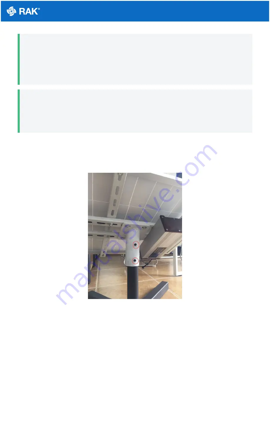
6. Mount the whole installation you have assembled on top of a circular pole. Put the panel facing up and insert

the pole in the pipe opening on the bottom of the construction. Make sure the pole is of a sufficiently small
diameter to fit with a recommended value of 65 millimeters. Use 6 pieces of M8-bolts to fix the bottom to the
construction as shown in the image below.

Figure 26: Installing Bolts in the Kit into the Vertical Circular Pole

Lightning Protection

In this document, we will be discussing how to set up your lightning surge protection system whether be your
RAK7249 WisGate Edge Max situated outdoor or indoor. Such protection system must be taken into consideration
to ensure a fully functional Gateway without interruption or damage from the lightings.

Содержание WisGate Edge Max

Страница 1: ...e inserting or ejecting the SIM card What s Included in the Package Figure 1 RAK7249 Package Contents NOTE The included type and number of antennas and the Backup Battery Kit is optional depending on...

Страница 2: ...stall the LoRa card The motherboard supports two LoRa cards Slot one supports only SPI type and slot two supports only USB type Figure 4 Installing the LoRa card 4 If your board supports the cellular...

Страница 3: ...e Wi Fi MAIN connector to connect the Wi Fi antenna 7 If you have a Backup Battery Kit connect with the backup battery to the motherboard 8 Fix the M3 hexagon spacers on the plate with four screws and...

Страница 4: ...e 10 Connect the PH2 0 socket on the motherboard and the charging PCB board with the 2pin signal cable Connect the DC socket of the charging PCB board and the battery socket with a DC Plug cable Plug...

Страница 5: ...to prevent leaks Figure 12 Closing the enclosure Installation Instructions on mounting and securing the mounting kit to the enclosure and the bearing pole 1 Fix the included cross bracket on the botto...

Страница 6: ...to the pole clamp Weather Protection To better protect the Ethernet cable gland and the antenna connector from the weather you need to cover them with PVC tape 1 Clean the surface area of the connect...

Страница 7: ...Wrap three additional layers with PVC tape with natural uncoiling force and a 50 overlap Make sure to cover the head and the tail of the connector Figure 18 Final PVC wrapping Solar Panel and Battery...

Страница 8: ...below are the detailed dimensions of the solar panel for extended functions Figure 20 Solar Panel Dimensions 2 Electrical Characteristics The table below is the electric characteristics of the Solar...

Страница 9: ...n Guide 1 Install the bolts in the holes which are circled in red in the following image below This will make an H shaped base for the Solar Panel to be mountable on the top The circular pipe in the m...

Страница 10: ...iling that is part of the bottom of the battery casing WARNING Tighten the bolts as possible as the battery is quite heavy Figure 22 Mounting the Battery to the Bracket 3 Connect the input port power...

Страница 11: ...panel entering the input terminal on the battery is performed in Step 3 Figure 24 Lithium Battery to Solar Panel Outside Connection 5 Connect the Lithium Battery output terminal cable to the input po...

Страница 12: ...h issues 6 Mount the whole installation you have assembled on top of a circular pole Put the panel facing up and insert the pole in the pipe opening on the bottom of the construction Make sure the pol...

Страница 13: ...ew terminal on the bottom right side of the Gateway casing to the grounding rail bar NOTE No additional protection for the Ethernet cabling is required at the Gateway side There is a surge protection...

Страница 14: ...n antenna and GPS receiver A surge protection device for securing transceiver against transients over voltage and surge currents induced by bolts of lightning For the purpose of protecting the indoor...

Страница 15: ...ems It is widely used in office and industry comprehensive network wiring projects or the similar telecommunication applications such as Gigabit Ethernet ATM ISDN and VoIP systems High performance chi...

Страница 16: ...and performed the procedures listed in the Outdoor Deployment Category Listed below are the individual sections for you to read depending on your Gateway application Gateway Installation Guide Solar P...

Страница 17: ...atives for you to choose depending on the availability of the requirements needed WARNING Do not power the device if the LoRa Antenna port has been left open to avoid potential damage in the RAK7249 W...

Страница 18: ...jector to your PC The default IP is 169 254 X X The last two segments X X are mapped from the last four bits of the MAC address of your gateway For example the last four bits of the MAC address are 0F...

Страница 19: ...or click Scan to choose your ESSSID select the right Encryption method and enter the correct Key Figure 38 Connect through Wi Fi Credentials NOTE Assuming you have entered the correct parameter values...

Страница 20: ...nd the other end to the PoE port of the PoE injector Connect the LAN port of the PoE injector to your router The router s DHCP server should assign an IP Address to the Gateway You can change the defa...

Отзывы: