


Service
26
6200
plus
Series
Service Manual
Power Supply
Overview
The 6200
plus
series chassis supports several power supply configurations:
•
A single PS/2 AC or DC power supply
•
A power supply enclosure with up to two (2) AC or DC independently redundant,
hot-swappable power supplies
Note:
If only one (1) power supply is installed, a blank panel covers the empty bay.
Features
All power supply configurations have the following features:
•
System Power ON/OFF Switch
: this rocker-style switch in the front panel control
area directs power from the DC output converter to the chassis interior.
•
ON: power is supplied to the chassis interior from the DC output converter
within the power supply.
•
OFF: power is removed from the chassis interior, but the DC output converter
within the power supply remains in operation.
•
Line Power ON/OFF Switch
: this rocker-style switch on the power supply directs
power from the external source to the DC output converter within the power supply.
•
ON: power is supplied to the DC output converter from the external source.
•
OFF: all power to the chassis is removed.
•
DC Output Power Harness
: this series of connectors supplies power to all internal
devices.
Indicators and
Controls
Operations for each hot-swappable power supply are indicated by a green LED in the
front panel control area and by an audible alarm:
•
An LED remains lit when its respective power supply is operating properly.
•
An LED will flash, or blink, when its respective power supply fails.
•
An audible alarm will sound when a power supply fails.
Note:
The audible alarm can be silenced by the red “Alarm Stop” button in the
front panel control area.
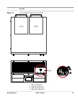
•
The power supplies are considered Left and Right as seen from the front of the
chassis (
Figure 17
).
More...
For more information, see the Power Supply Addendum.
Alarm indicators and controls may also be provided on the power supply
enclosure. See the Power Supply Addendum for more information.
Содержание 6200plus Series
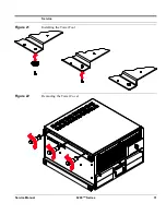
Страница 17: ...Service Service Manual 6200plus Series 9 Figure 4 Removing the Top Cover ...
Страница 23: ...Service Service Manual 6200plus Series 15 Figure 9 Installing the Expansion Card Retention Bracket ...
Страница 25: ...Service Service Manual 6200plus Series 17 Figure 10 Removing the Media Drawer ...
Страница 27: ...Service Service Manual 6200plus Series 19 Figure 11 Removing the 3 Drive Bay ...
Страница 28: ...Service 20 6200plus Series Service Manual Figure 12 Installing Drives ...
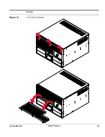
Страница 33: ...Service Service Manual 6200plus Series 25 Figure 16 Air Filter Installation ...
Страница 40: ...Service 32 6200plus Series Service Manual Notes ...


