© 2003 Radionics, a division of Detection Systems, Inc.
PO Box 80012, Salinas, CA 93912-0012, USA
Customer Service: (800) 538-5807; Technical Support: (888) 886-6189
50084D
Installation Guide
04/03
D6680
Page 4 of 4
3.4.1
Installation Instructions
Remove AC power and lock out the circuit breakers prior to installation.
1. Mount the gang box to the
wall or supporting
structure.
2. Insert a gang box partition
into the gang box. The
partition will divide the
gang box into two
sections. The large
section contains the high
voltage wiring; the small
section contains the low
voltage wiring.
3. Punch out a conduit
knockout in the high
voltage side of the gang
box. Bring the 110 VAC
wiring through the
knockout hole and into the
gang box as required by
the local Authority Having
Jurisdiction, NFPA and the
NEC.
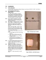
Gang Box
Cover Plate
Transformer
Duplex Outlet
Low Voltage
Section
Cover
Gang Box
Partition
Figure 7: D8004 Installation
4. Connect the isolated 110 VAC wiring to the duplex outlet.
5. Mount the duplex outlet to the cover plate using the #6 machine screws, nuts and lockwashers provided.
Mount the cover plate to the gang box with the #10 screws provided with the gang box.
6. Energize the power to the circuit(s) and, using a voltmeter, test the duplex outlet for proper voltage.
7. Punch out a conduit knockout in the low voltage side of the gang box. Bring the low voltage wiring through
the knockout hole and into the gang box as required by the local Authority Having Jurisdiction, NFPA and
the NEC.
8. Connect the low voltage wiring to the transformer.
9. Plug the transformer into the bottom outlet of the duplex outlet. Secure the transformer to the duplex outlet
using the screw provided.
10. Attach the cover to the cover plate with the four #6 self-tapping screws provided.
4.0
Programming
Refer to the
D6600 NetCom System Guide (P/N: 46542) for information on how to program the D6680.
5.0
Additional UL Requirements
The D6680 must be installed in the same room as the D6600 Central Station Receiver and within
50 ft. (15.2 m) of the D6600 Central Station Receiver.
5.1
UL 864 Fire System Installations
The D6680 must be installed in accordance with NFPA 72.
5.1.1
Required Accessories
•
AE1 or AE2 Enclosure
•
D8004 Transformer Housing


