7
RadioLink Electronic Ltd
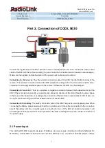
a brushed DC motor must be correctly selected to avoi
d damage to the ESC. At the same time, the "M+” lead
wire of the motor interface is connected to the positive pole of the motor (usually a yellow or red power supply
line), and the "M-" lead wire is connected to the negative pole of the motor (usually a blue or black power
supply line). In addition, the brushed DC motor load connected to the motor interface of the ESC must not
have an additional circuit connection with the input power port, otherwise the ESC system will not operate
normally.
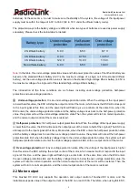
Regarding the matching relationship between the speed of the brushed DC motor (conventional model) and
the power battery (conventional lithium battery and Ni-MH battery), please refer to the following table:
Lithium battery
Ni-MH battery
Motor speed
2S lithium battery
5-6S Ni-MH battery
RPM < 30000 , 7.2 V
3S lithium battery
7-9S Ni-MH battery
RPM < 20000 , 7.2 V
4S lithium battery
10-12S Ni-MH battery
RPM < 15000 , 7.2 V
Note
: The table is for reference only. When in specific application scenarios, users need to analyze the
concrete cases to prevent the ESC and motor from being damaged or even battery damage accidents.
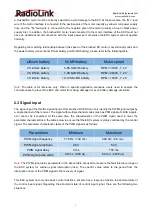
2.3 Signal input
The signal input (the throttle signal input) of this brushed DC ESC can only identify the PWM signal output by
a single channel of the receiver. The signal with multiple channel codes (such as PPM signals, S.BUS signals,
etc.) cannot be recognized. At the same time, the characteristics of the PWM signal need to meet the
parameter characteristics in the table below to ensure that the ESC system is stably controlled by the control
signal. The parameter characteristic table of the PWM signal is as follows:
Parameters
Minimum
Maximum
PWM signal frequency
7.15 Hz
(
140 ms
)
400 Hz
(
2.5 ms
)
PWM signal amplitude
2.8 V
5.4 V
PWM signal delay
0 ms
150 ms
PWM signal pulse width
0.8 ms
(
800 us
)
2.2 ms
(
2200 us
)
Note
: The PWM signal delay parameters in the above table are used to measure the fault tolerance range of
the ESC system for sudden signal interruption (loss). The specific value refers to the period from the
interruption (loss) of the PWM signal to the recovery of signal.
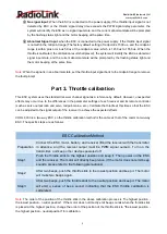
This ESC system not only has basic control functions, but also has a response function to abnormal state of
the control input signal. Regarding the abnormal state of control input signal, there are the following two
situations:

