background image

14

Receiver

Output Level.............. ............................................................ 
............................. 1 ± 0.2 Vpp (Audio), 1 ± 0.2 Vpp (Video)
S-Video Output Level......................... ................................... 
...................................Y: 1 Vpp ± 0.2 Vpp, C: 228 mV ± 20%

IR Extender

Output Level...................................................... ..0 - 10 dBm
Operating Frequency............................. ........... 433.92 MHz
Modulation Type...............................................................AM
Effective Operating Range... ................................................ 
........................ Approx. 100 ft (30.48 m) (clear line of sight)
Receiving Sensitivity...............................................<-80 dBm

Specifications are subject to change and improvement without notice. 

Actual product may vary from the images found in this document.

FCC Information

This equipment has been tested and found to comply with the limits for a Class B 

digital device, pursuant to Part 15 of the FCC Rules. These limits are designed to 

provide reasonable protection against harmful interference in a residential installa-

tion. This equipment generates, uses, and can radiate radio frequency energy and, 

if not installed and used in accordance with the instructions, may cause harmful 

interference to radio communications. However, there is no guarantee that interfer-

ence will not occur in a particular installation. If this equipment does cause harmful 

interference to radio or television reception, which can be determined by turning 

the equipment off and on, the user is encouraged to try to correct the interference 

by one or more of the following measures:

• Reorient or relocate the receiving antenna.

• Increase the separation between the equipment and receiver. 

• Connect the equipment into an outlet on a circuit different from that to which the 

receiver is connected. 

• Consult your local 

RadioShack

 store or an experienced radio/TV technician for 

help.

If you cannot eliminate the interference, the FCC requires that you stop using your 

equipment. Changes or modifications not expressly approved by 

RadioShack

 may 

cause interference and void the user’s authority to operate the equipment.

15-332 -EN 033110.indd   14

4/6/2010   5:25:18 PM

Содержание 1500332

Страница 1: ...z Wireless A V Signal Sender Thank you for purchasing your A V Signal Sender from RadioShack Please read this user s guide before installing setting up and using your new sender 2 3 15 332 EN 033110 i...

Страница 2: ...nstall the Transmitter 1 Make sure the transmitter is off then connect the transmitter to your A V source DVD player TV or VCR with the RCA cable For better picture quality connect your transmitter to...

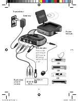
Страница 3: ...3 Transmitter Antenna Power Indicator IR Extender Front side pointing at A V source IR sensor within 50 cm 15 o OR OR OR Back view of A V source 15 332 EN 033110 indd 3 4 6 2010 5 25 02 PM...

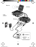
Страница 4: ...4 Receiver Antenna Power Indicator IR sensor 15 332 EN 033110 indd 4 4 6 2010 5 25 09 PM...

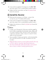
Страница 5: ...ed side faces the transmitter nNotes S Video and Composite Video are interchangeable but S Video is usually the dominant input There will no picture output at the receiver if your A V device only has...

Страница 6: ...the receiver or transmitter and A V device jacks white for audio left red for audio right yellow for video For optimum performance and reception keep the transmitter and receiver away from wireless LA...

Страница 7: ...mote control not included at the receiver and make a selection nNote Most A V devices work on 38kHz Your transmitter is set to 38kHz by default indicated by B position of the A B Remote switch If the...

Страница 8: ...D DSS or LDP with the supplied RCA cable For better picture quality connect your transmitter to the A V source with a S Video cable not included 2 Use another cable not supplied to connect your VCR DV...

Страница 9: ...9 ANT ANT Transmitter Receiver Recommended TV connection for dual output VCR 15 332 EN 033110 indd 9 4 6 2010 5 25 17 PM...

Страница 10: ...power plug and signal cables are firmly connected Check if the channel of transmitter and receiver are set to the same channel Make sure that all cables are connected correctly Check if there is any...

Страница 11: ...damage to the device Check if the supplied voltage matches the adapter specification Select a different channel by sliding the channel switch on both transmitter and receiver If using a microwave ove...

Страница 12: ...sary to press and hold each button for about a second The working angle of the IR Sensor is 15 o and the working distance is no more than 16 4 feet 5m Check the path between the transmitter and receiv...

Страница 13: ...s warranty If your A V signal sender is not performing as it should take it to your local RadioShack store for assistance Specifications Power Supply 12 V DC 300 mA Weight Transmitter Rceiver 7 oz 200...

Страница 14: ...ccordance with the instructions may cause harmful interference to radio communications However there is no guarantee that interfer ence will not occur in a particular installation If this equipment do...

Страница 15: ...n the U S RadioShack will at its option unless otherwise provided by law a repair the product without charge for parts and labor b replace the product with the same or a comparable product or c refund...

Страница 16: ...s which vary from State to State You may contact RadioShack at RadioShack Customer Relations 300 RadioShack Circle Fort Worth TX 76102 04 08 www RadioShack com Printed in China 04A10 1500332 2010 Radi...

Отзывы: